
Pedal system and vehicle with the pedal system

a pedal system and pedal system technology, applied in the field of pedal systems, can solve the problems of insufficient consideration of holding motion and sense of incongruity, and achieve the effects of easy operation, easy operation, and easy to bring about susceptibility to fatigu

Inactive Publication Date: 2006-10-19
HITACHI LTD
View PDF9 Cites 27 Cited by
  • Summary
  • Abstract
  • Description
  • Claims
  • Application Information

AI Technical Summary

Benefits of technology

The invention is a pedal system that can adjust the characteristics of the pedal and vehicle movement based on the driver's intentions for stepping, releasing, and holding motions. This system aims to provide a better driving experience that is easy to operate, non-fatiguing, and provides a good feeling of driving. The system can also adapt to different vehicle and environmental information to ensure a seamless driving experience.

Problems solved by technology

That is, there is caused a problem that since an operating direction of a pedal is resulted from control on the pedal system, delay occurs in reaction of the pedal relative to a pedal manipulation by a driver if the pedal system is controlled on the basis of the operating direction of the pedal, and stepping and releasing motions intended by the driver does not necessarily correspond to an actual operating direction, thus bringing about a sense of incongruity.
However, there is caused a problem that consideration is not adequately given to a holding motion in the case where stepping on a pedal is maintained constant.

Method used


Image

  • Pedal system and vehicle with the pedal system
  • Pedal system and vehicle with the pedal system
  • Pedal system and vehicle with the pedal system

Examples


Embodiment Construction

[0032] A vehicle operation control apparatus according to the invention has a mechanical and electrical construction that enables detecting a pedal travel and a pedal effort and electrically controlling an actuator, realizes a pedal travel corresponding to a pedal effort, generates a pedal reaction force corresponding to a pedal travel, and generates a braking force and a driving force on the basis of a pedal travel and a pedal effort.

[0033] A main construction of an embodiment, to which the invention is applied, will be described below with reference to the drawings.

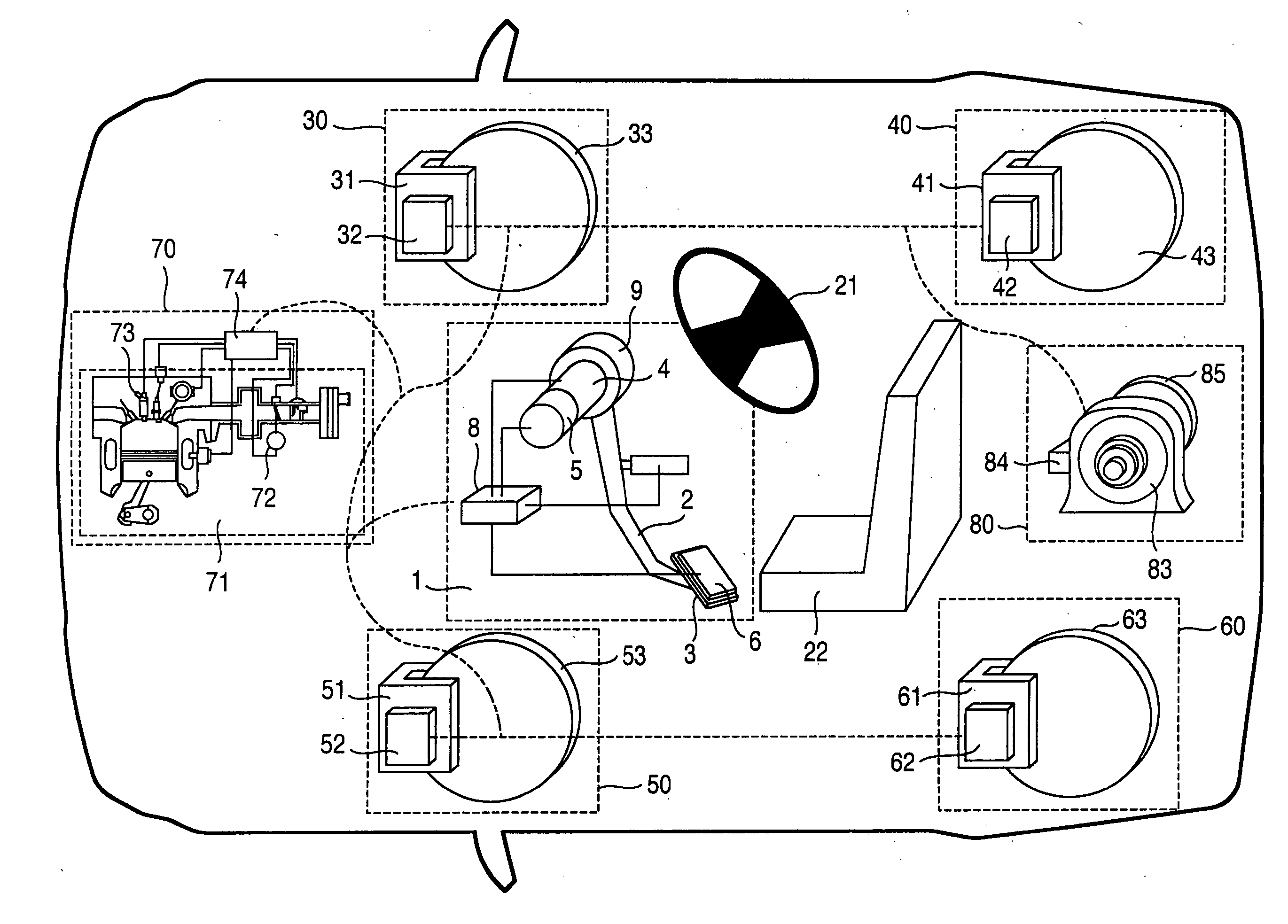
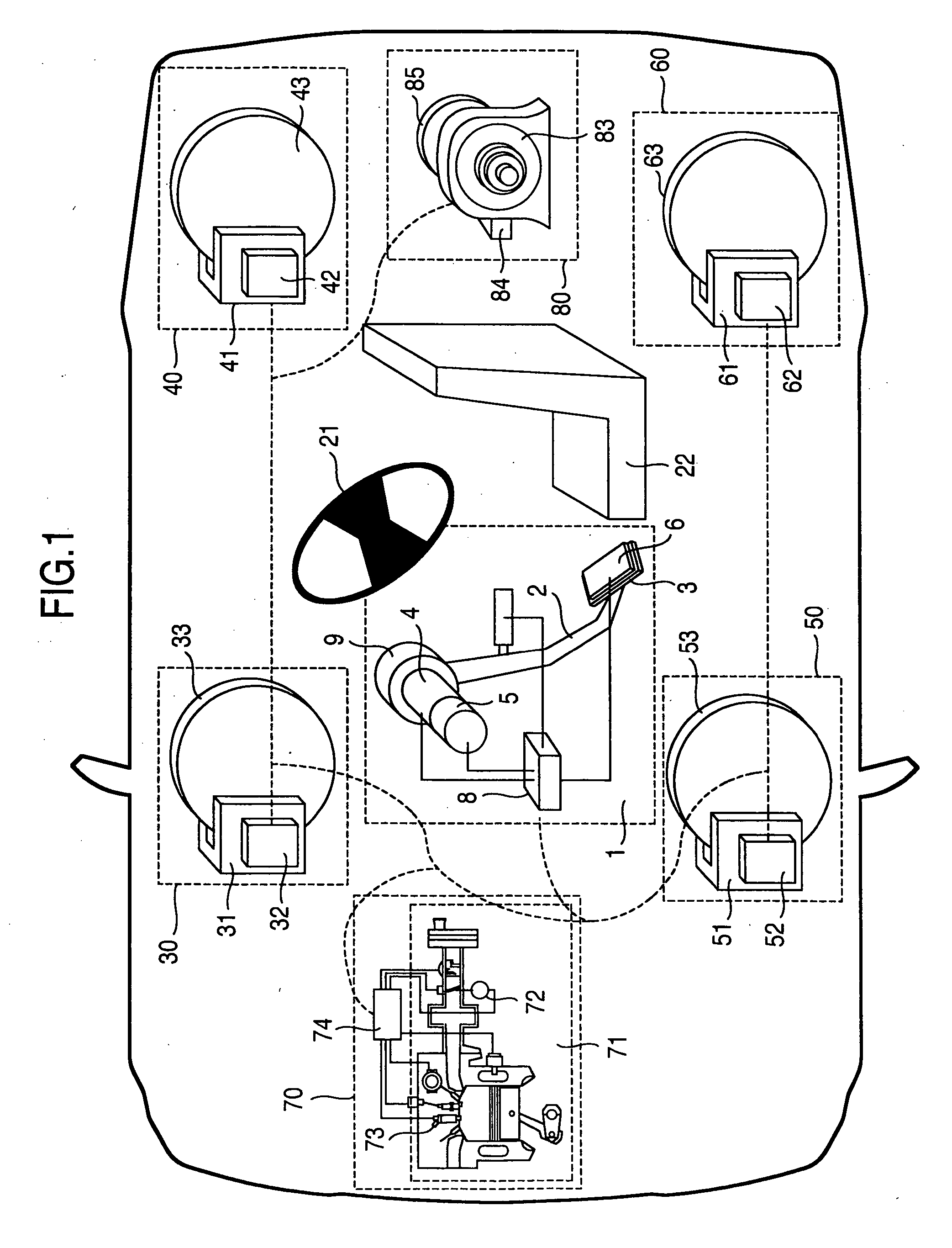
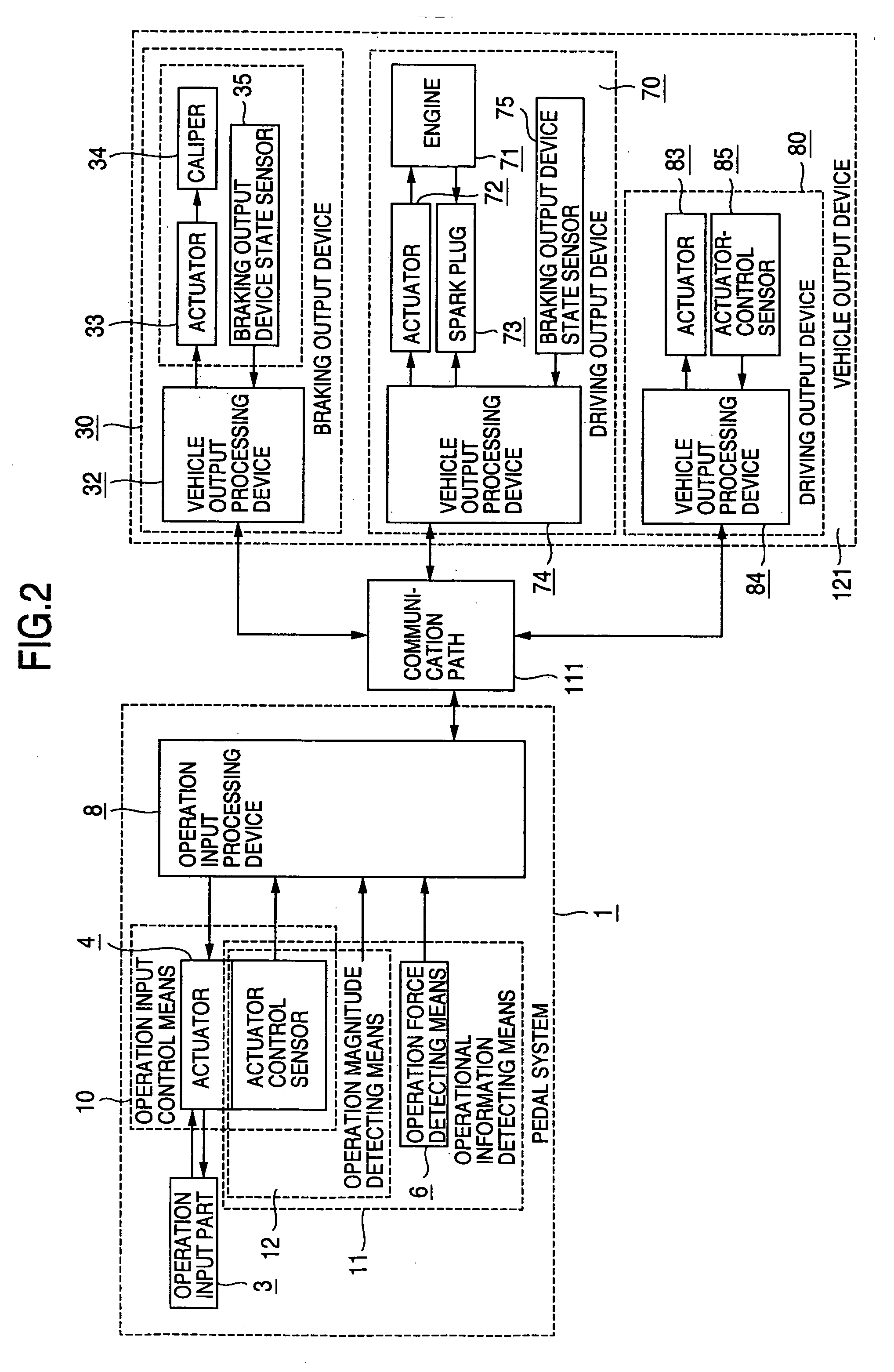
[0034]FIG. 1 is a schematic view showing a system that constitutes the invention. FIG. 2 is a block diagram of the system that constitutes the invention.

[0035] The reference numeral 1 denotes a pedal system, which a driver manipulates in order to operate a vehicle. With the pedal system 1, a pedal effort generated upon stepping by a driver varies a pedal travel and a pedal velocity in predetermined ranges. The pedal ...


PUM


Abstract

For a pedal travel, a pedal reaction force, a driving force of a vehicle, and a braking force of a vehicle, different characteristics conformed to a stepping motion, a releasing motion, and a holding motion are determined on the basis of a pedal effort and predetermined characteristics of a pedal reaction force, and characteristics in a holding motion are changed according to vehicle information and environmental information.

Description

BACKGROUND OF THE INVENTION [0001] The present invention relates to a pedal system capable of electrically controlling a pedal travel or a pedal reaction force or a vehicle output, and a vehicle provided with the pedal system. [0002] Conventionally, a driving force and a braking force of a vehicle are operatively manipulated by a pedal. Stepping on a pedal, a driver physically feels an inertial force generated by acceleration and deceleration of a vehicle as well as a pedal reaction force. Therefore, properties such as a pedal travel, a pedal reaction force, a driving force and a braking force of a vehicle, etc. constitute factors that determine a feeling of driving, easiness of operation, susceptibility to fatigue, etc. [0003] On the other hand, since a conventional pedal is mechanically connected to an accelerator wire and a master cylinder, characteristics of the pedal is uniquely determined by the mechanism. [0004] In recent years, however, a technique, so-called bi-wire, makes ...

Claims


Application Information

Patent Timeline
Patent Type & Authority Applications(United States)
IPC IPC(8): F02D11/10B60K26/04B60T7/06B60T8/17B60T8/32B60W30/00B60W30/16G05G1/30G05G7/04
CPCB60T7/042Y10T74/20528Y10T74/20888Y10T74/20534Y10T74/20558
Inventor UENO, KENTAROSASAKI, MITSUHIDE
Owner HITACHI LTD
Learn More