Touch sensing apparatus with differential signal source

a technology of differential signal source and touch sensor, which is applied in the field of touch sensing apparatus, can solve the problems of poor resolution of sensor, relatively high cost of resistive membrane touch sensor, and poor user experien

Inactive Publication Date: 2006-10-12
GOLD CHARM LTD
View PDF10 Cites 8 Cited by
  • Summary
  • Abstract
  • Description
  • Claims
  • Application Information

AI Technical Summary

Benefits of technology

[0008] A touch sensing apparatus is provided. A preferred embodiment of the touch sensing apparatus includes one or more touch sensing units, a detector, and a signal processing unit. Each touch sensing unit comprises: a differential signal source for generating two signals which have a same frequency but reverse phases; and two sensors for receiving a touch signal of a user's finger. One sensor is connected to an anode of the differential signal source, and the other sensor is connected to a...

Problems solved by technology

However, these sensors generally have poor resolution.
In addition, the sensor surface is exposed to the user and is thus subject to wear.
Further, resistive-membrane touch sensors are relatively expensive.
This cannot be guaranteed in app...

Method used


Image

  • Touch sensing apparatus with differential signal source
  • Touch sensing apparatus with differential signal source
  • Touch sensing apparatus with differential signal source

Examples


Embodiment Construction

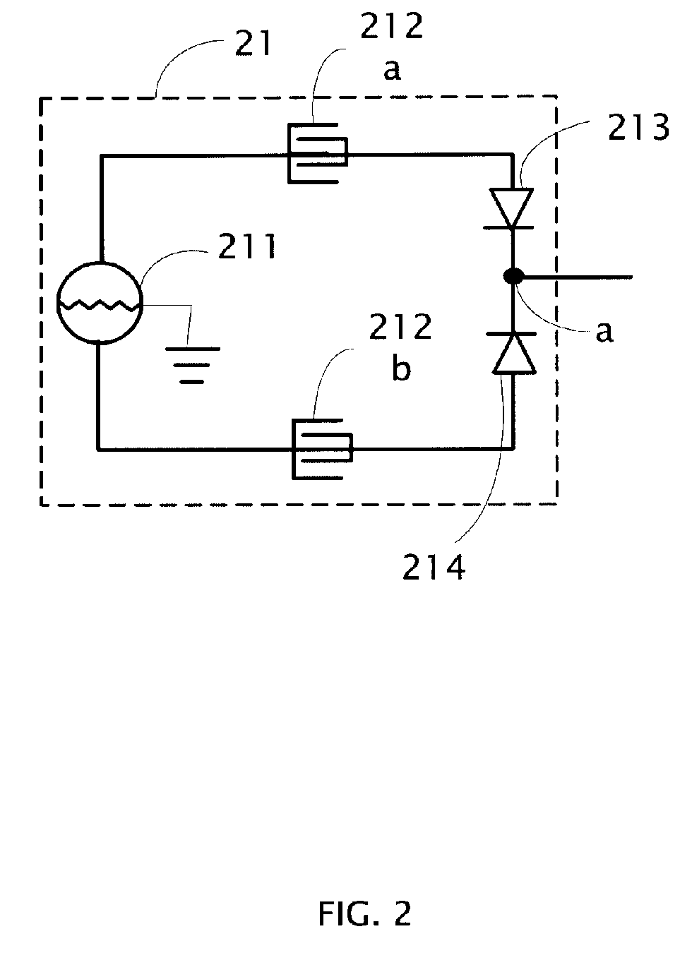
[0014]FIG. 2 is an exemplary circuit diagram of a touch sensing unit in accordance with a preferred embodiment of the present invention. The touch sensing unit 21 mainly includes a signal source 211, two sensors 212a, 212b each having two terminals, a first diode 213, and a second diode 214. The first and second diodes 213, 214 respectively possess an anode and a cathode. The signal source 211 possesses a first terminal and a second terminal. In the preferred embodiment, one of the first and second terminals also functions as an output terminal, for outputting a signal to a reference signal detector 30 (see FIG. 3). The signal source 211 is grounded. The first and second terminals of the signal source 211 are respectively connected with first terminals of the two sensors 212a, 212b. The anodes of the two diodes 213, 214 are respectively connected to second terminals of the two sensors 212a, 212b. Additionally, the cathodes of the two diodes 213, 214 are connected with each other, an...


PUM


Abstract

A preferred embodiment of the touch sensing apparatus includes one or more touch sensing units, a detector, and a signal processing unit. Each touch sensing unit comprises: a differential signal source for generating two signals which have a same frequency but reverse phases; and two sensors for receiving a touch signal of a user's finger. One sensor is connected to an anode of the differential signal source, and the other sensor is connected to a cathode of the differential signal source. The detector is for converting the received signal into a digital signal. An input terminal of the detector is connected to the sensors of each touch sensing unit. The signal processing unit is for determining which sensor is touched according to the frequency and phase of the signal output from the detector. The signal processing unit is connected to an output terminal of the detector. The touch sensing unit may further include a reference signal circuit.

Description

TECHNICAL FIELD [0001] The present invention relates generally to touch sensing apparatuses such as those used in certain personal computers, and particularly to a touch sensing apparatus for determining which of sensors thereof is touched according to a frequency and a phase of an input signal. DESCRIPTION OF RELATED ART [0002] There are several available touch-sense technologies which may be employed for use as a position indicator in an apparatus such as a personal computer. Resistive-membrane position sensors are known and used in several applications. However, these sensors generally have poor resolution. In addition, the sensor surface is exposed to the user and is thus subject to wear. Further, resistive-membrane touch sensors are relatively expensive. A one-surface sensor configuration requires a user to be grounded relative to the sensor for reliable operation. This cannot be guaranteed in applications such as with portable computers. An example of a one-surface sensor conf...

Claims


Application Information

Patent Timeline
IPC IPC(8): G09G5/00
CPCG06F3/044
Inventor HSIEH, KUAN-HONGLIN, SHI-QUANWANG, HAN-CHELI, XIAO-GUANG
Owner GOLD CHARM LTD
Why Eureka
Try Eureka