
Response surfaces for orthodontic treatment planning

a technology of orthodontic treatment and response surfaces, applied in the field of orthodontic treatment planning, can solve the problems of insufficient tension, few tools for orthodontists, and use of headgear

Inactive Publication Date: 2006-10-05
3M INNOVATIVE PROPERTIES CO
View PDF11 Cites 97 Cited by
  • Summary
  • Abstract
  • Description
  • Claims
  • Application Information

AI Technical Summary

Benefits of technology

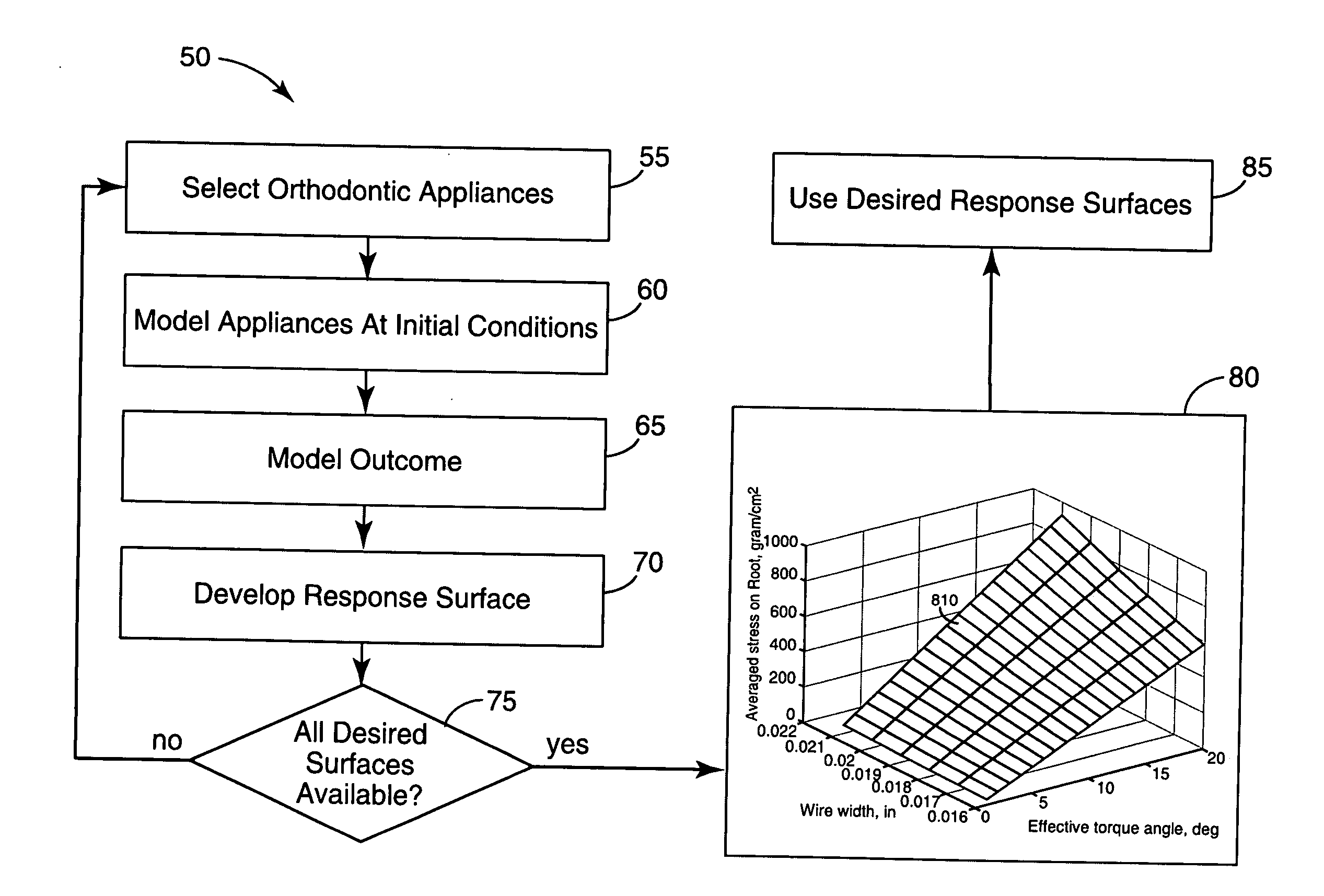
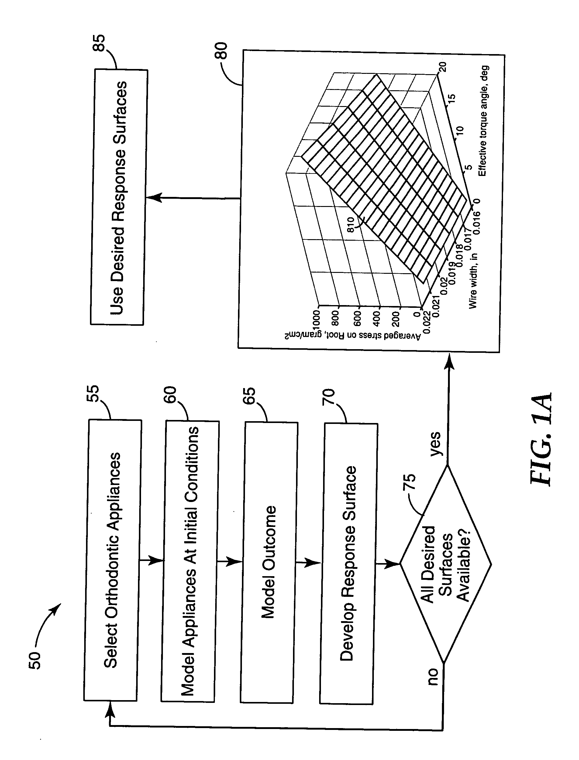
[0011] The present invention is directed to methods and apparatus for orthodontic treatment planning. Embodiments of the present invention include those that employ methods for determining tooth movement and orthodontic prescriptions using response surfaces. According to one embodiment, a numerical method for determining movement of an orthodontic structure involves determining an initial position of an orthodontic structure, determining an altered position of the orthodontic structure, and generating response surface data using a mathematical relationship between the initial position and the altered position. The mathematical relationship may be defined b...

Problems solved by technology

Instead of using headgear, which is often considered unsatisfactory because it is visibly apparent, many practitioners and patients favour the use of intra-oral devices for correcting Class II and Class III malocclusions.
These modules are typically removable by the patient for replacement when necessary, since the module may break or the elastomeric material may degrade during use to such an extent that the amount of tension exerted is not sufficient.
However, few tools exist to assist the orthodontist in the accurate selection of appliances that are likely to effectively implement the orthodontist's initial treatment strategy.
Moreover, few tools exist to allow the orthodontist to accurately predict the effectiveness of the initial treatment strategy.

Method used


Image

  • Response surfaces for orthodontic treatment planning
  • Response surfaces for orthodontic treatment planning
  • Response surfaces for orthodontic treatment planning

Examples


Embodiment Construction

[0026] In the following description of the illustrated embodiments, reference is made to the accompanying drawings, which form a part hereof, and in which is shown by way of illustration, various embodiments in which the invention may be practiced. It is to be understood that the embodiments may be utilized and structural changes may be made without departing from the scope of the present invention.

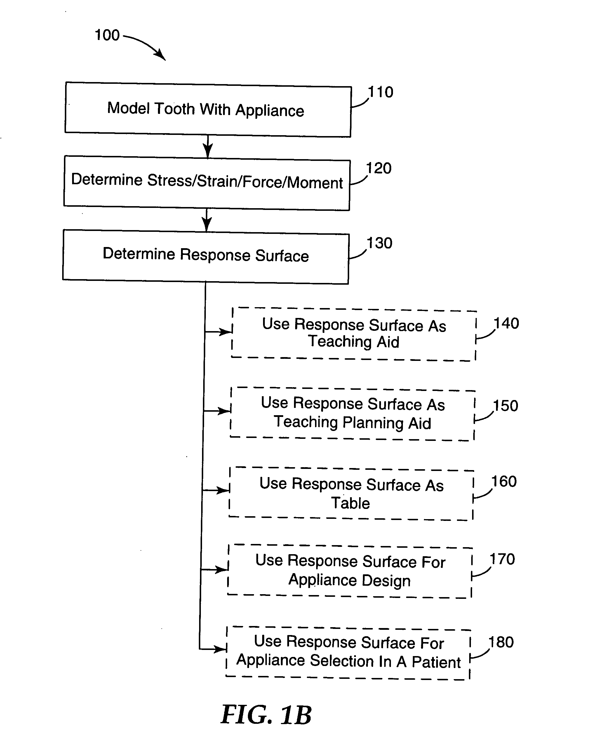
[0027] The present invention relates to orthodontic treatment planning methods and devices. More particularly, the present invention relates to using response surfaces for orthodontic treatment planning, and / or appliance selection, and / or prescription validation. A response surface is a two or more dimensional output defined as a function of input parameters. For example, a mathematical relationship may define output parameters as a function of input parameters. A response surface may use the mathematical relationship to express the output in the form of data, graph, table, computed nume...


PUM


Abstract

Methods and apparatus for orthodontic treatment planning that involve determining an initial position of an orthodontic structure, determining an altered position, and generating response surface data using a mathematical relationship between the positions. The mathematical relationship may be defined by a number of parameters useful for determining one or more of the stress, strain, force, and moment associated with movement of the orthodontic structure. The mathematical relationship between the initial position and the altered position may be defined using a finite element analysis, empirically determined, or using other computational methodologies such as a finite difference methodology. The mathematical relationship may also be defined using an analytical methodology, such as elasticity and / or plasticity methodologies. Response surface data may be generated as a teaching aid, treatment planning aid, table, or other useful form, which may be useful, for example, for designing an orthodontic appliance, verifying an orthodontic prescription, and / or planning the prescription.

Description

FIELD OF THE INVENTION [0001] The present invention relates to orthodontic treatment planning methods and, more particularly, to devices and methods for determining tooth movement and orthodontic prescriptions using response surfaces. BACKGROUND [0002] Orthodontics is a branch of dentistry that involves the movement of malpositioned teeth to orthodontically correct positions. Before prescribing an orthodontic treatment, X-rays and photographs of the patient's teeth and jaw structure are typically taken. Also, a mold of the patient's teeth is typically made. This mold, along with the X-rays and photographs, provide a model of the positions of the patient's teeth and dental arches prior to treatment. [0003] The orthodontist also relies on a post treatment model of the altered positions of the patient's teeth and dental arches. This post-treatment model has typically been a mental model formulated in the mind of the orthodontist based on the orthodontist's experience and skill. However...

Claims


Application Information

Patent Timeline
IPC IPC(8): A61C3/00
CPCA61C7/00A61C7/002A61C7/28A61C7/146A61C7/12
Inventor LAI, MING-LAICHEN, ANDREW W.TRICE, JENNIFER L.HAREGOPPA, GOPAL B.
Owner 3M INNOVATIVE PROPERTIES CO
Learn More