Liquid ejection head

a liquid ejection head and head technology, applied in printing and other directions, can solve the problems of increasing the probability of increasing the load on the control system of the head, the head structure and the circuit composition become more complicated, etc., and achieve the effect of variable ejection characteristics

Inactive Publication Date: 2006-10-05
FUJIFILM CORP
View PDF0 Cites 12 Cited by
  • Summary
  • Abstract
  • Description
  • Claims
  • Application Information

AI Technical Summary

Benefits of technology

[0025] According to this aspect of the present invention, when the thickness t1 of the upper layer is smaller than the thickness t2 of the lower layer, materials for the upper layer and the lower layer are selected in such a manner that the elasticity coefficient E1 of the upper layer is higher than the elasticity coefficient E2 of the lower layer, and it is thereby possible to ensure a prescribed amount of displacement of the tongue section with respect to a prescribed temperature change by selecting.
[0026] According to the present invention, a composition is adopted in which the size of the supply flow channel is varied when the temperature of the liquid changes, by deformation of the tongue section, which constitutes a portion of the walls of the supply flow channel and has a laminated structure of two layers having different coefficients of linear expansion, by the bimetal-like effect due to the change in the ink temperature. Therefore, variations in ejection characteristics caused by change in the viscosity of the liquid due to change in the temperature of the liquid are cancelled out by alteration of the size of the supply flow channel, and hence prescribed ejection characteristics can be ensured, even if the temperature of the liquid changes.

Problems solved by technology

If a control circuit or control system of this kind is used, then not only do the head structure and the circuit composition become more complicated, but also, there is a probability of increasing the load on the control system of the head.

Method used


Image

  • Liquid ejection head
  • Liquid ejection head
  • Liquid ejection head

Examples


Embodiment Construction

[0046] Below, an inkjet recording apparatus having a liquid ejection head according to the present invention is described in detail, with reference to the accompanying drawings. FIG. 1 is a schematic drawing showing a general view of the inkjet recording apparatus 10.

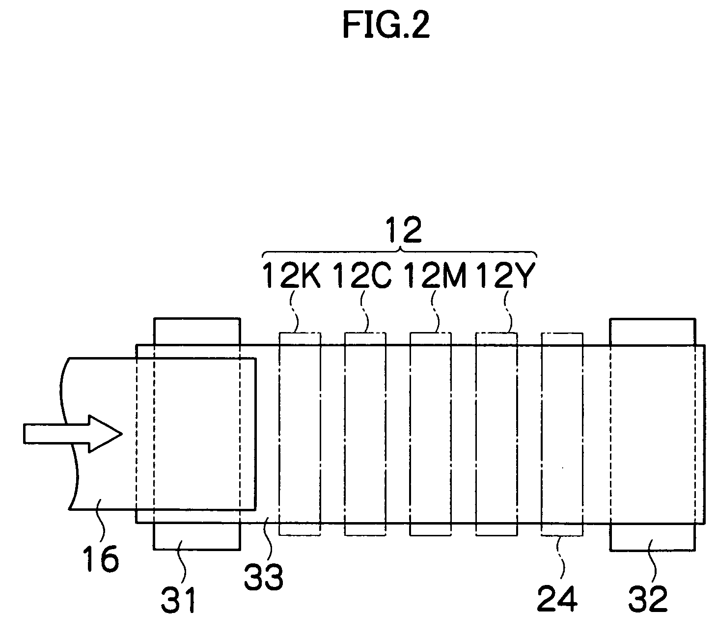
[0047] As shown in FIG. 1, the inkjet recording apparatus 10 comprises: a printing unit 12 having a plurality of print heads (liquid ejection heads) 12K, 12C, 12M, and 12Y for ink colors of black (K), cyan (C), magenta (M), and yellow (Y), respectively; an ink storing and loading unit 14 for storing inks of K, C, M and Y to be supplied to the print heads 12K, 12C, 12M, and 12Y; a paper supply unit 18 for supplying recording paper 16; a decurling unit 20 for removing curl in the recording paper 16 supplied from the paper supply unit 18; a suction belt conveyance unit 22 disposed facing the nozzle face (ink droplet ejection face) of the print unit 12, for conveying the recording paper 16 while keeping the recording paper...


PUM


Abstract

The liquid ejection head comprises: a pressure chamber which accommodates liquid to be ejected through an ejection aperture; a diaphragm which constitutes a wall of the pressure chamber; a supply port which is formed as an opening section in a portion of the diaphragm; a supply flow channel which is provided between the supply port and the pressure chamber; and a common liquid chamber which accommodates the liquid to be supplied to the pressure chamber through the supply port and the supply flow channel and is arranged on a side of the diaphragm reverse to a side thereof adjacent to the pressure chamber, wherein the diaphragm has a tongue section, a portion of a perimeter of the tongue section being surrounded by the supply port, the tongue section constituting a portion of a wall of the supply flow channel, a portion of the diaphragm forming the tongue section having a laminated structure of an upper layer on the side adjacent to the common liquid chamber and a lower layer on the side adjacent to the pressure chamber, a coefficient of linear expansion α1 of the upper layer and a coefficient of linear expansion α2 of the lower layer satisfying a relationship of α1<α2, at least a portion of the tongue section being bendable in a direction to change a size of the supply flow channel.

Description

BACKGROUND OF THE INVENTION [0001] 1. Field of the Invention [0002] The present invention relates to a liquid ejection head, and more particularly, to liquid ejection technology for a liquid ejection apparatus and head, which suppresses change in ejection characteristics due to change in the liquid temperature. [0003] 2. Description of the Related Art [0004] An inkjet recording apparatus is known, which comprises an inkjet head (liquid ejection head) having an arrangement of a plurality of nozzles and which records images on a recording medium by ejecting ink from the nozzles toward the recording medium while causing the inkjet head and the recording medium to move relatively to each other. [0005] In the inkjet recording apparatus, ink is supplied to pressure chambers from an ink tank, through an ink supply channel, and by driving actuators by supplying electrical signals corresponding to the image data to the actuators, the pressure chambers are caused to deform, thereby reducing t...

Claims


Application Information

Patent Timeline
Patent Type & Authority Applications(United States)
IPC IPC(8): B41J2/045
CPCB41J2002/14193B41J2/14233B41J2/045
Inventor KODAMA, KENICHI
Owner FUJIFILM CORP
Why Eureka
Try Eureka