
Multi-modality ablation device

a multi-modal, ablation technology, applied in the field of medical instruments, can solve the problems of radio frequency energy not reaching lesion transmurality, unable to achieve lesion transmurality, and unable to ablate thicker tissue at the expense of lesion width, so as to minimize the activation time, reduce the effect of ablation cycle time and reduce the effect of excessive peripheral thermal damage to tissu

Inactive Publication Date: 2006-09-28
ETHICON INC
View PDF9 Cites 7 Cited by
  • Summary
  • Abstract
  • Description
  • Claims
  • Application Information

AI Technical Summary

Benefits of technology

The present invention provides ablation devices and methods that use both ultrasonic and radio-frequency energy to create lesions in tissue with minimal adverse effects such as excessive peripheral thermal damage to tissue. The devices and methods selectively direct the energy to the tissue surface using an ultrasonic transducer and a radio-frequency electrode, which can be powered separately or simultaneously. The instruments have one or more switches for selectively coupling the ultrasonic and radio-frequency energy sources to the tissue surface. The methods also involve measuring the tissue thickness and applying the energy based on the measured thickness. The invention provides improved ablation devices and methods that overcome the disadvantages of conventional instruments.

Problems solved by technology

However, this modality can only ablate thicker tissue at the expense of lesion width.
Creating wider lesions with radio frequency energy may result in damage to critical peripheral tissue structures.
Beyond 6 mm in tissue depth, radio frequency energy may not achieve lesion transmurality.
However, for thin tissue, ultrasound may be ineffective as the ultrasound energy is focused in blood, not in the tissue.

Method used


Image

  • Multi-modality ablation device
  • Multi-modality ablation device
  • Multi-modality ablation device

Examples


Embodiment Construction

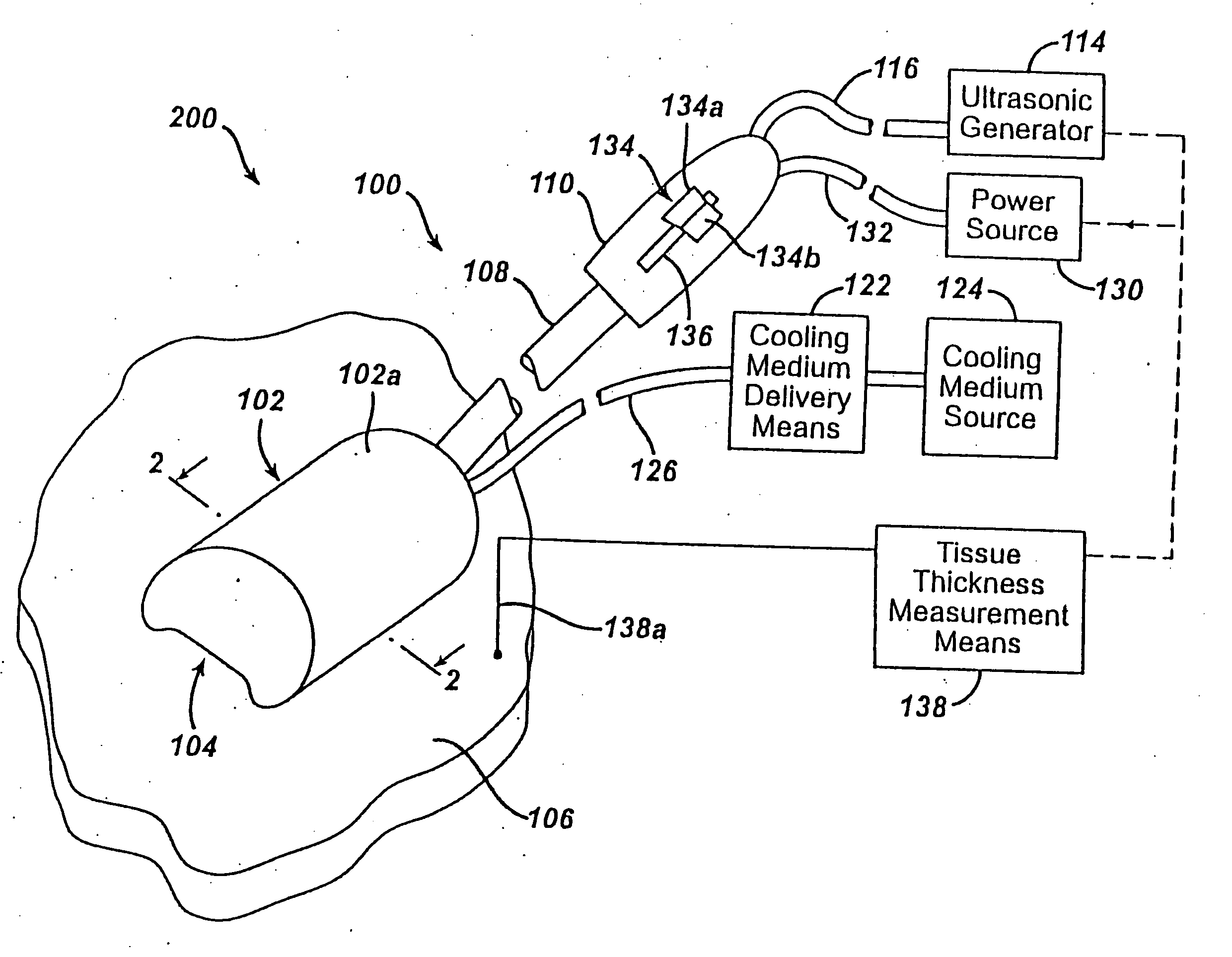
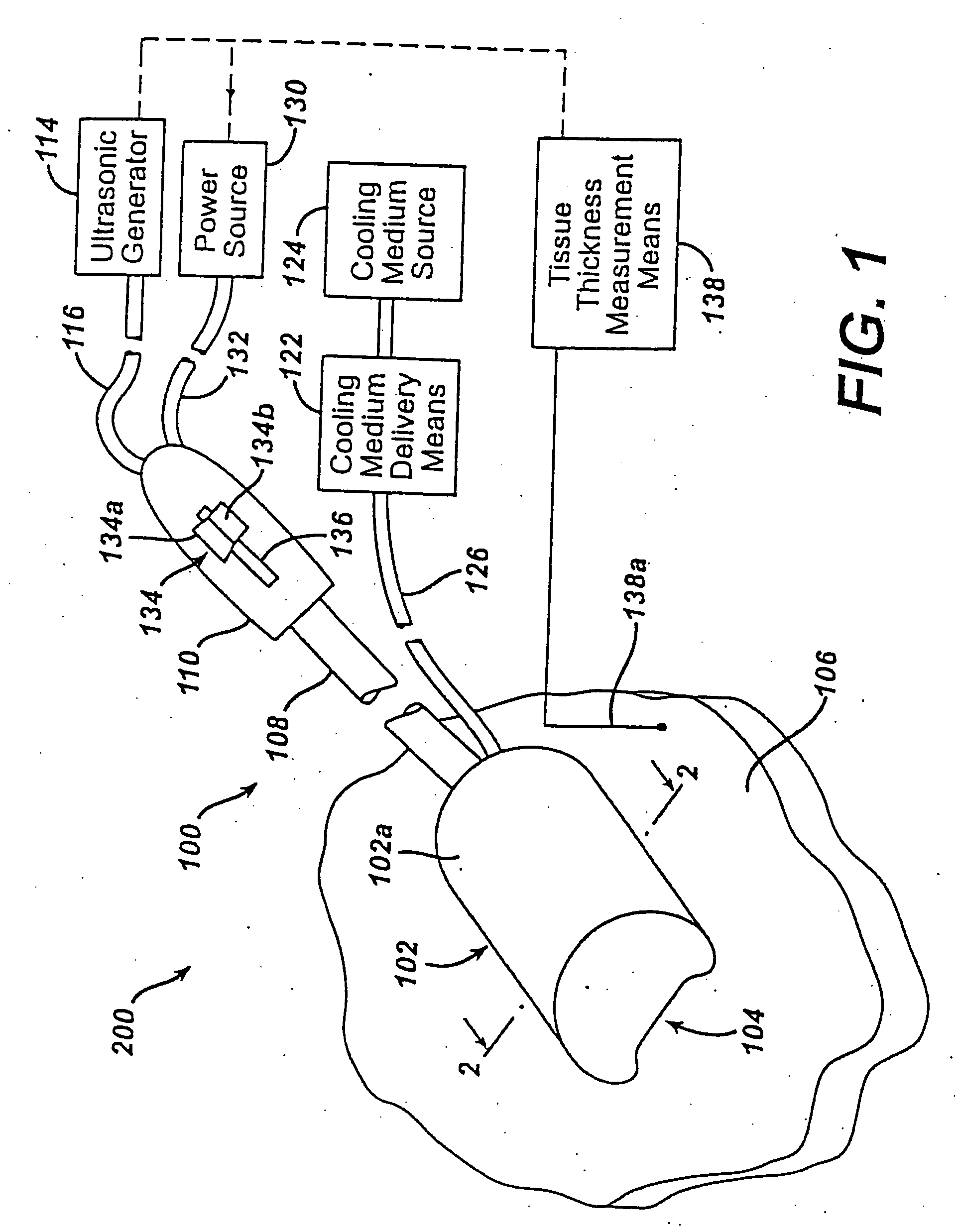
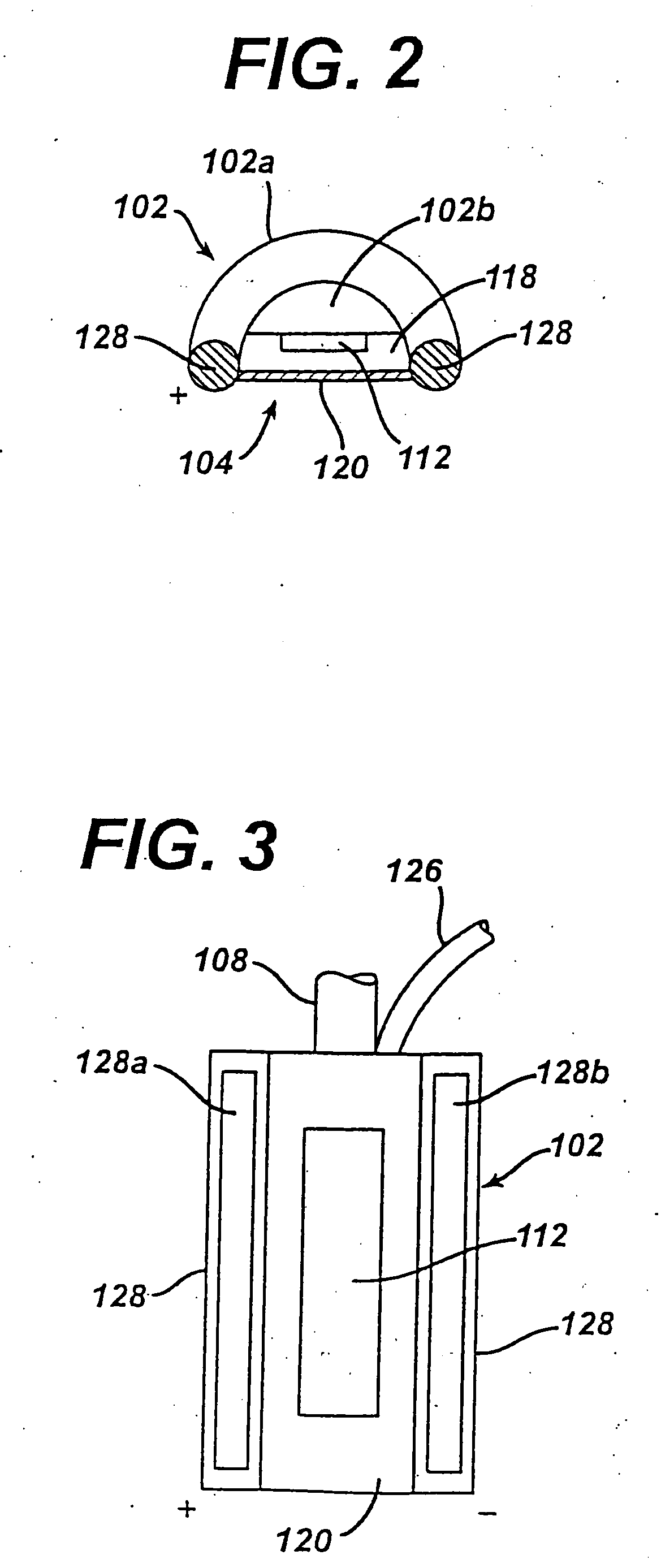
[0028] Referring now to FIGS. 1-3, therein is illustrated an instrument and system for ablation of tissue, the instrument generally referred to by reference numeral 100 and the system generally referred to by reference numeral 200. Although the instrument 100 is shown and described as a rigid instrument, it can also be configured in other ways without departing from the scope or spirit of the present invention. For example, the instrument 100 may be configured as a catheter, a minimally invasive instrument, or a less invasive instrument. The instrument 100 has a body 102 having at least one surface 104 for contacting a tissue surface 106. The surface is substantially planar, but may be slightly curved to follow a contour of a curved tissue surface. The body 102, as configured by way of example only, is disposed at a distal end of an elongated tube 108. The elongated tube 108 has a handle 110 disposed at a proximal end thereof. The body 102 preferably comprises a non-conductive head ...


PUM


Abstract

An instrument for ablation of tissue. The instrument including: a body having at least one surface for contacting a tissue surface, the at least one surface being substantially planar; an ultrasonic transducer disposed in the body for generating ultrasonic energy and directing at least a portion of the ultrasonic energy to the tissue surface, the ultrasonic transducer being operatively connected to an ultrasonic generator; at least one radio-frequency electrode disposed on the at least one surface for directing radio frequency energy to the tissue surface, the at least one radio-frequency electrode being operatively connected to a power source; and one or more switches for selectively coupling at least one of the ultrasonic transducer to the ultrasonic generator and the at least one radio-frequency electrode to the power source.

Description

BACKGROUND OF THE INVENTION [0001] 1. Field of the Invention [0002] The present invention relates generally to medical instrumentation, and more particularly, to a multi-modality ablation device. [0003] 2. Prior Art [0004] Ultrasonic and radio frequency instruments are well known in the medical arts. Such instrumentation may be used to make lesions in tissue, but are also used to cut and coagulate tissue and blood, respectively. Typically, ultrasonic instrumentation has an ultrasonic transducer at a working end of the instrument, while radio frequency instruments have one or more electrodes at a working end of the instrument. Each of the working ends is typically separated from a handle or other manipulation means by an elongated shaft. [0005] Instruments utilizing radio frequency energy perform well for single-sided ablation of thin tissue. However, this modality can only ablate thicker tissue at the expense of lesion width. Creating wider lesions with radio frequency energy may re...

Claims


Application Information

Patent Timeline
Patent Type & Authority Applications(United States)
IPC IPC(8): A61B18/04A61B18/14A61B18/00A61B19/00A61N7/02
CPCA61B8/546A61B18/14A61B2018/00011A61B2019/5276A61N7/02A61B2019/461A61B2090/061A61B2090/378
Inventor WASHINGTON, EBONIAKWOK, JONATHANPODANY, VACLAV O.PENDEKANTI, RAJESH
Owner ETHICON INC
Learn More