
Electronic display system

a display system and electronic technology, applied in the field of motor vehicles, can solve the problems of not revealing nor suggesting a display having information that changes in real-time and according to a predetermined threshold vehicle, and driving is often stuck in traffi

Inactive Publication Date: 2006-09-28
MCCANN KEITH H
View PDF21 Cites 91 Cited by
  • Summary
  • Abstract
  • Description
  • Claims
  • Application Information

AI Technical Summary

Benefits of technology

[0010] The electronic display system includes a programmable electronic display, driven by an electronic display driver, and an electronic control module that allows information to be sent to and shown on the electronic display. The electronic control module is coupled either to the vehicle's speedometer, to a tachometer either coupled to the driveshaft instead of the crankshaft or when a brake sensor determines that the brake is released, or to a sensor that determines the rate at which the driveshaft rotates, which allows the control module to determine whether a threshold speed has been reached.

Problems solved by technology

However, such conventional plates, signs, or display devices for vehicles typically display an invariable message or image, except for the roof-mounted billboard kind of sign frequently displayed on taxi cabs and other commercial vehicles, which require manual replacement of a paper sign mounted within the billboard frame.
Additionally, drivers are often stuck in traffic for long periods of time or stopped at intersections and are forced to view the same standard advertisements or vehicle identity information displayed on the automobile.
Additionally, WIPO PCT patent WO 96 / 36030, dated November 1996, discloses an electronic license plate system with an ID device embedded in the plate, however does not disclose nor suggest a display having information that changes in real-time and according to a predetermined threshold vehicle speed.

Method used


Image

  • Electronic display system
  • Electronic display system
  • Electronic display system

Examples


Embodiment Construction

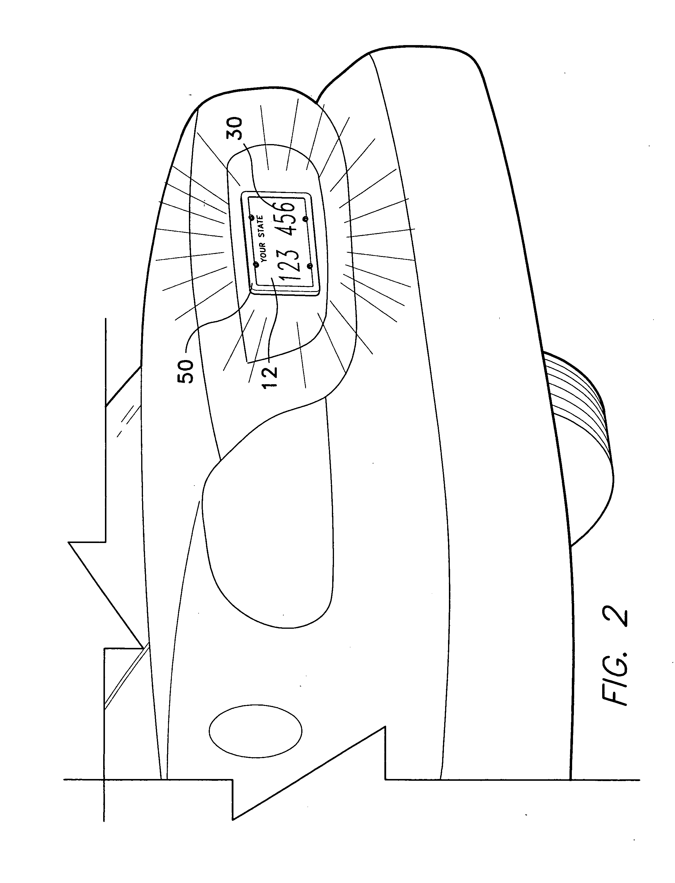
[0021] The present invention is an electronic display system, designated generally as 10 in the drawings, that generally displays rotating advertisements or the like until a predetermined threshold speed is exceeded. Once the threshold speed of the vehicle is exceeded, an electronic display alternatively displays vehicle license plate information, such as the license plate number and State in which the vehicle is registered.

[0022] Referring first to FIG. 1, a block diagram of the electronic display system 10 is shown. The electronic display system 10 includes a programmable electronic display 12 and an electronic control module 14 that allows information to be sent to and shown on the electronic display 12. The electronic display 12 may be a liquid crystal display, an LED display, or any other electronic display device that can show text, graphics, images or the like. The electronic display 12 is generally mounted either to the front or back of a vehicle, and preferably is mounted ...


PUM


Abstract

The electronic display system displays advertisements, traffic and weather information on a display panel mounted to the license plate support of an automobile or any vehicle when the vehicle is moving beneath a predetermined threshold speed. The display can be mounted elsewhere, for example, anywhere on the rear or sides of a larger vehicle such as a van, bus or truck, where it will be readily seen. Once the vehicle exceeds the predetermined threshold speed, the display changes, showing vehicle license plate information, such as the license plate number, State of registration, etc. The electronic display system includes a programmable electronic display, driven by a display driver, and an electronic control module that allows information to be sent to and shown on the electronic display. The electronic control module is coupled to a speedometer, a tachometer, or a sensor that determines the rate at which the drive shaft rotates, which allows the control module to determine whether the threshold speed has been reached.

Description

CROSS-REFERENCE TO RELATED APPLICATION [0001] This application claims the benefit of U.S. Provisional Patent Application Ser. No. 60 / 637,454, filed Dec. 21, 2004.BACKGROUND OF THE INVENTION [0002] 1. Field of the Invention [0003] The present invention relates to a display device for a motor vehicle, and particularly to an electronic display system for displaying information that can be reprogrammed, and that may include advertising or other commercial notices. [0004] 2. Description of the Related Art [0005] Conventional license plates for conveying vehicle identification are well known. License plates including some form of electronic device for illuminating at least a portion of the display area of the plate and information display devices mounted onto automobiles, such as buses, are also known. Further, bumpers of cars, windows, etc. often bear signs used to display the vehicle owner's preference for political candidates or causes, for places to vacation, or for favored establishm...

Claims


Application Information

Patent Timeline
IPC IPC(8): G09F21/04
CPCB60R13/00B60R13/10G09F21/04
Inventor MCCANN, KEITH H.
Owner MCCANN KEITH H
Learn More