Display

a display and display technology, applied in the field of display, can solve the problems of disadvantageous visual recognition of flickering caused by low-frequency driving, disadvantageous limit in power consumption reduction, etc., and achieve the effect of simplifying the circuit structure and reducing power consumption

Inactive Publication Date: 2006-09-21
SANYO ELECTRIC CO LTD
View PDF10 Cites 15 Cited by
  • Summary
  • Abstract
  • Description
  • Claims
  • Application Information

AI Technical Summary

Benefits of technology

[0014] The present invention has been proposed in order to solve the aforementioned problems, and an object of the present invention is to provide a display capable of rendering flickering hard to visually recognize, reducing power consumption and simplifying the structure of a circuit for negatively / positively reversing images.

Problems solved by technology

When the liquid crystal display is driven by the conventional line inversion driving method shown in FIG. 13 at a low frequency in order to reduce power consumption, however, flickering is disadvantageously easy to visually recognize.
When the pixel voltage supply source is remarkably fluctuated, the brightness of light passing through the pixel portions A to F deviates from a desired level, to cause flickering.
When the liquid crystal display is driven by this conventional dot inversion driving method, flickering caused by low-frequency driving can be rendered hard to visually recognize since this flickering nonlinearly takes place.
Therefore, reduction of power consumption is disadvantageously limited also when the liquid crystal display is driven at a low frequency in order to reduce power consumption.
In order to negatively / positively reverse images in the aforementioned liquid crystal display employing the conventional dot inversion driving method, further, the driver IC must disadvantageously be provided therein with a video signal inversion circuit including inverter circuits of the same number as the bit number of the video signal.
In order to negatively / positively reverse a 6-bit video signal, for example, the driver IC must include a video signal inversion circuit having six inverter circuits in order to invert the video signal, and hence the structure of the video signal inversion circuit is complicated and the driver IC remarkably consumes power when reversing the images.

Method used


Image

  • Display
  • Display
  • Display

Examples


Embodiment Construction

[0029] An embodiment of the present invention is now described with reference to the drawings.

[0030] The structure of a liquid crystal display according to the embodiment of the present invention is described with reference to FIGS. 1 to 4. The liquid crystal display according to this embodiment is described as an example of the inventive display.

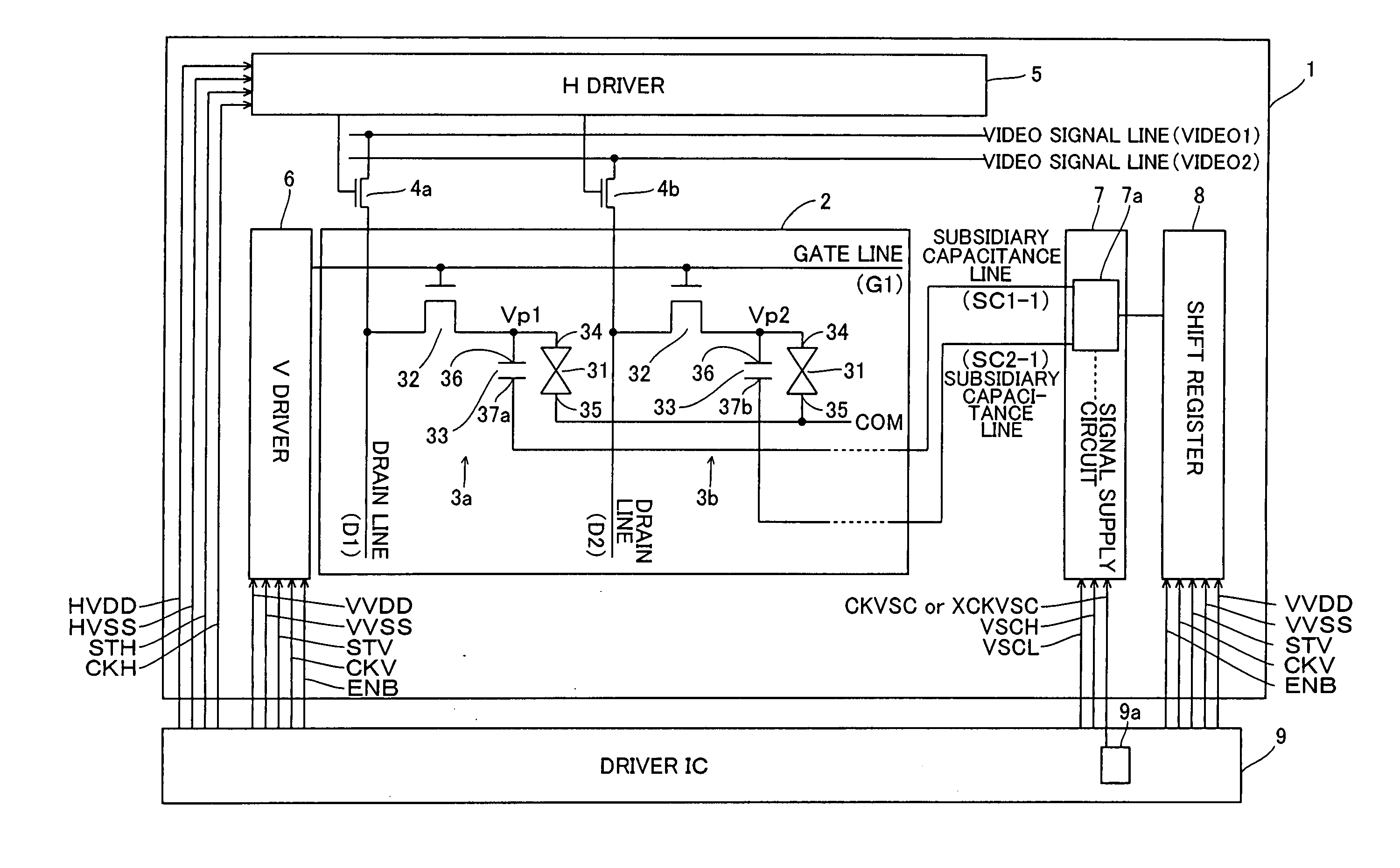
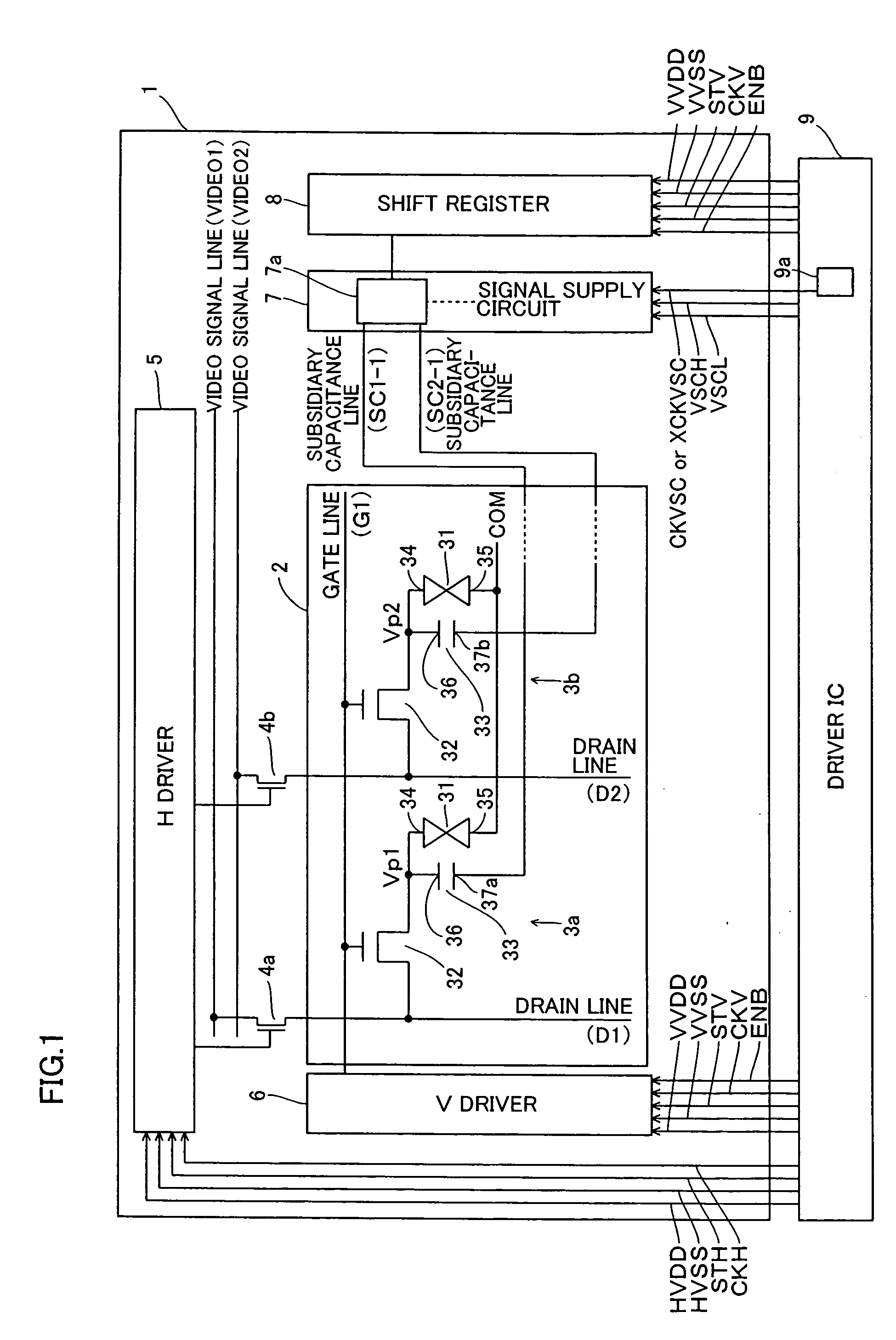
[0031] Referring to FIG. 1, a display portion 2 is provided on a substrate 1 in the liquid crystal display according to this embodiment. Pixel portions 3a and 3b are arranged on the display portion 2. While FIG. 1 shows only one gate line G1, two drain lines D1 and D2 intersecting with the gate line G1 and the two pixel portions 3a and 3b arranged along the gate line G1 in order to simplify the illustration, a plurality of gate lines and a plurality of drain lines are arranged to intersect with each other and a plurality of sets of pixel portions 3a and 3b are adjacently arranged in the form of a matrix in practice. The pixel portions 3a ...


PUM


Abstract

A display capable of rendering flickering hard to visually recognize, reducing power consumption and simplifying the structure of a circuit for negatively / positively reversing an image is provided. This display comprises a plurality of drain lines and a plurality of gate lines, a first pixel portion and a second pixel portion each including a subsidiary capacitor having a first electrode and a second electrode and a first subsidiary capacitance line and a second subsidiary capacitance line connected to the subsidiary capacitors of the first pixel portion and the second pixel portion respectively. The display also comprises a signal supply circuit supplying either a first signal or a second signal for negatively / positively reversing an image to the first subsidiary capacitance line of the first pixel portion when displaying the image while supplying either a third signal or a fourth signal for negatively / positively reversing the image to the second subsidiary capacitance line of the second pixel portion when reversing the image.

Description

CROSS-REFERENCE TO RELATED APPLICATIONS [0001] The priority application number JP2004-346154 upon which this patent application is based is hereby incorporated by reference. BACKGROUND OF THE INVENTION [0002] 1. Field of the Invention [0003] The present invention relates to a display, and more particularly, it relates to a display having a pixel portion. [0004] 2. Description of the Background Art [0005] A liquid crystal display comprising a pixel portion including a liquid crystal layer is generally known as a display. In the conventional liquid crystal display, the liquid crystal layer of the pixel portion is held between a pixel electrode and a common electrode. The conventional liquid crystal display changes the arrangement of liquid crystal molecules by controlling a voltage (video signal) applied to the pixel electrode of the pixel portion, thereby displaying an image responsive to the video signal on a display portion. [0006] When the aforementioned liquid crystal display app...

Claims


Application Information

Patent Timeline
Patent Type & Authority Applications(United States)
IPC IPC(8): G09G3/36
CPCG09G3/3614G09G3/3655G09G3/3677G09G2300/0876G09G2310/06G09G3/20G09G3/36
Inventor UEKURI, TAMOTSUTSUTSUI, YUSUKEKITAGAWA, MAKOTO
Owner SANYO ELECTRIC CO LTD
Why Eureka
Try Eureka