
Machine for making steel hoop circumferential reinforcing elements

Inactive Publication Date: 2006-09-21
CLECO MFG
View PDF5 Cites 23 Cited by
  • Summary
  • Abstract
  • Description
  • Claims
  • Application Information

AI Technical Summary

Benefits of technology

[0017] In yet another embodiment the objects of this invention are achieved in a process for the automatic manufacture of steel reinforcing hoops wherein a coil of steel wire is fed from a decoiling device by pulling using a set of opposing rollers, through a sec

Problems solved by technology

The problem is that such steel mesh is expensive to make and to use and there has been an on-going attempt to reduce the cost of the manufacture of the cementitious elements for manhole construction.
Of course, the problem with the above is that it is more labor intensive and hence also costly and there has been a pressing need to have something that will manufacture these reinforcing hoops automatically in order to save the additional labor costs.

Method used


Image

  • Machine for making steel hoop circumferential reinforcing elements
  • Machine for making steel hoop circumferential reinforcing elements
  • Machine for making steel hoop circumferential reinforcing elements

Examples


Embodiment Construction

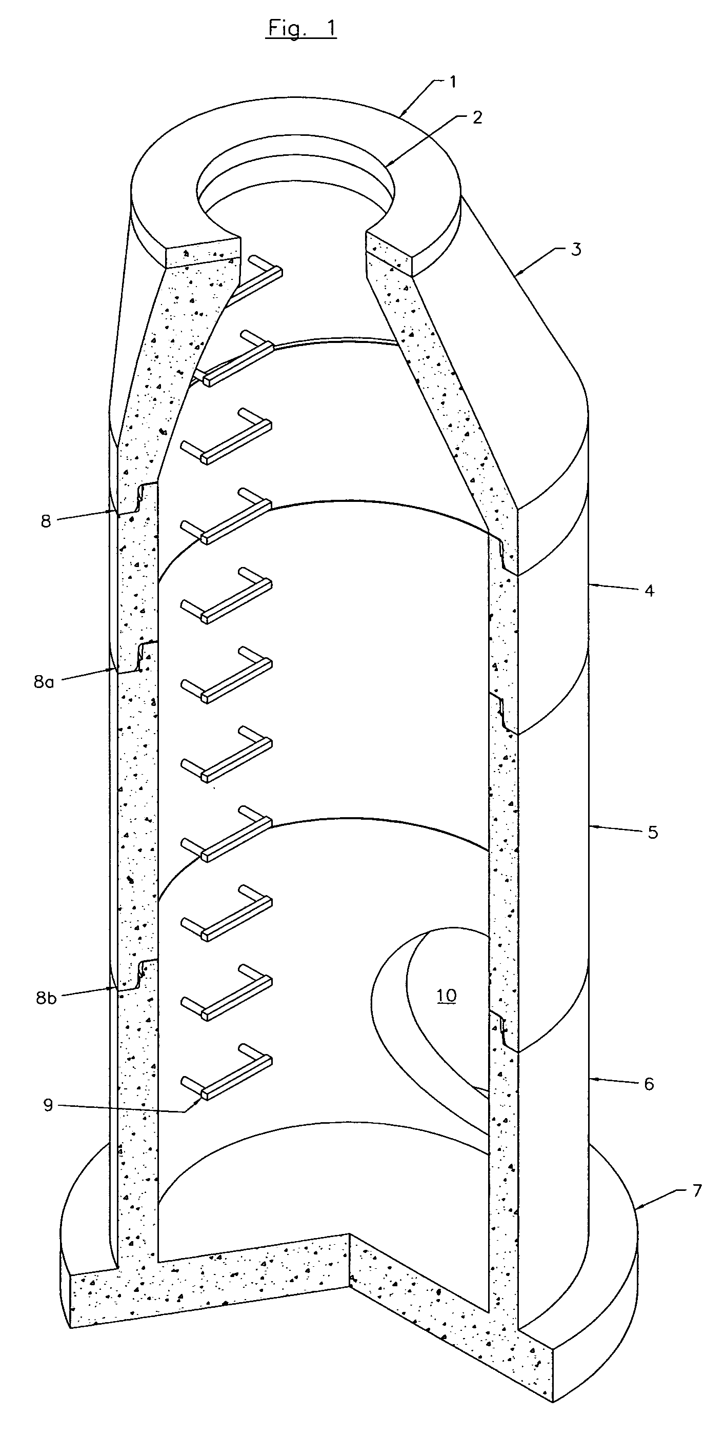
[0025] Looking now specifically at the drawings accompanying this invention, which show particularly preferred embodiments, but to which I am not limited, FIG. 1 is a cutaway view of a typical manhole the components of which may contain the reinforcing hoops of this invention. In this drawing, going from top to bottom, or from ground level to under ground level, I is the grade ring having an opening 2 through which one can enter the manhole. 3 is an eccentric cone top followed by two riser sections 4 and 5, which are shown as different lengths (2′ and 4′) in this drawing. 6 is a 4′ extended base section with a foot 7 to permit a firm footing under ground. The connection and mating elements of each section are shown as 8, 8a and 8b. A series of entry steps, one of which is shown as 9, permit easy entry into the manhole for servicing. One, of what may be a plurality of pipe openings, is shown as 10. The reinforcing hoop elements made by the teachings of this invention are useful in fo...


PUM

PropertyMeasurementUnit
Diameteraaaaaaaaaa
Diameteraaaaaaaaaa
Diameteraaaaaaaaaa

Abstract

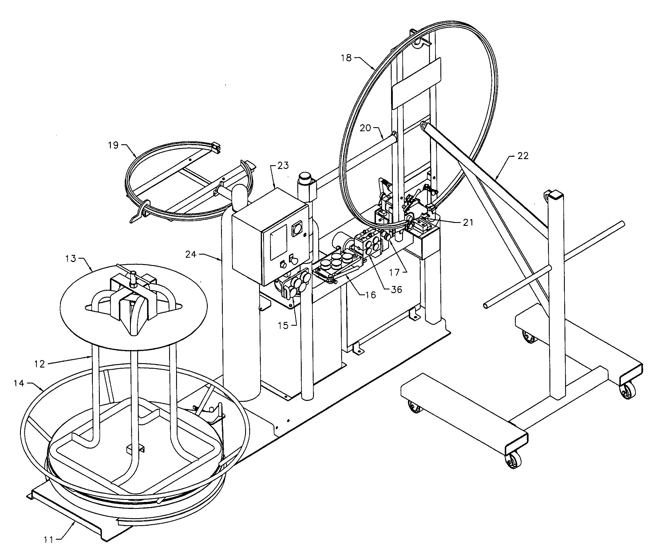
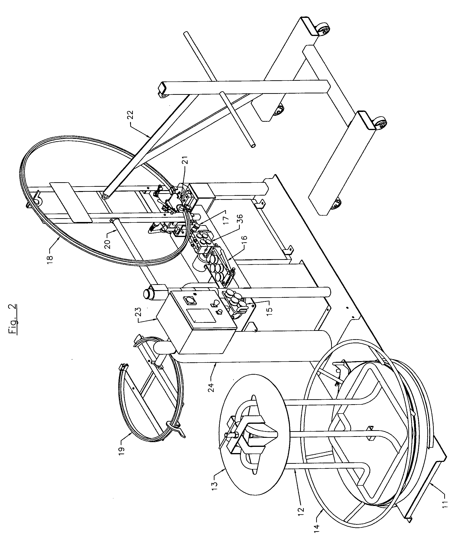
An automatic hoop forming machine comprising a wire decoiling and feeding element connected to a series of rollers designed to pull, take out some irregularities and partially impart a curve before said wire is fed on to a hoop guide roll of the desired diameter to form a hoop-shaped element. The ends are overlapped and welded prior to cutting. Any number of hoops may be formed automatically and are eminently useful as reinforcing members within cementitious materials used to make manholes, for example.

Description

BACKGROUND OF THE INVENTION [0001] 1. Field of the Invention: [0002] This invention relates to the field of the reinforcement of concrete and other cementitious materials or mixed cementitious materials. More specifically, this invention relates to the reinforcement of cementitious elements such as, for example, manhole elements such as risers, conical tops and grade rings therefore. Still more specifically, this invention relates to circular or hoop shaped circumferential reinforcing elements for such manhole risers, conical tops and grade rings (hereafter called “manhole elements”) therefore and to a unique and automated method for making such hoop shaped circumferential reinforcing elements. [0003] 2. Description of the Prior Art: [0004] Manhole elements are used within the industry to provide access to drains such as sewers or storm water drains. These manhole elements conventionally comprise a series of cementitious sections that interlock and come up from under the ground and ...

Claims


Application Information

Patent Timeline
IPC IPC(8): B21F37/00
CPCB21F3/00B21F37/00
Inventor CARR, DENNIS
Owner CLECO MFG
Learn More