
There dimensional image signal producing circuit and three-dimensional image display apparatus

a three-dimensional image and signal technology, applied in the field of display, can solve the problems of not being able to view with correct stereoscopic depth, unable to produce a realistic stereoscopic view for all screen sizes, and unable to achieve the effect of achieving stereoscopic depth,

Inactive Publication Date: 2006-09-14
TOMITA SEIJIRO
View PDF5 Cites 228 Cited by
  • Summary
  • Abstract
  • Description
  • Claims
  • Application Information

AI Technical Summary

Benefits of technology

[0029] According to the invention, the arrangement allows the left-eye image and the right-eye image to be displayed at a different timing to control easily the offsetting of the left-eye image and the right-eye image.

Problems solved by technology

When the same video content is reproduced on displays of different screen sizes in particular, a parallax between right- and left-eye images varies from one screen size to another, so that a stereoscopic depth (or a degree to which the image appears to pop out of the screen) changes according to the changing screen size, failing to produce a realistic stereoscopic view for all screen sizes.
That is, because stereoscopic video contents for use in large-scale amusement facilities are produced to suite large screens on which they are to be displayed, they cannot be viewed with correct stereoscopic depths unless displayed on large screens of the intended size in theaters or on apparatus.
When the screen size is too large, the stereoscopic sensation obtained is too strong causing dizziness or headache while too small a screen size fails to give the viewer a satisfactory three-dimensional effect.
As described above, since no techniques have been available for adjusting the parallax used in the already produced video content as the video is being reproduced, there is no alternative but to adjust the three-dimensional effect by changing a distance between the viewer's position and the screen.
Further, in broadcasting a three-dimensional video, there has been no technique available for automatically adjusting the three-dimensional effect according to various screen sizes of 3D displays so that the 3D video can be seen by multiple viewers.
It is therefore difficult to broadcast three-dimensional videos to unspecified multiple viewers.

Method used


Image

  • There dimensional image signal producing circuit and three-dimensional image display apparatus
  • There dimensional image signal producing circuit and three-dimensional image display apparatus
  • There dimensional image signal producing circuit and three-dimensional image display apparatus

Examples


Embodiment Construction

[0048] Embodiments of the present invention will be described by referring to the accompanying drawings.

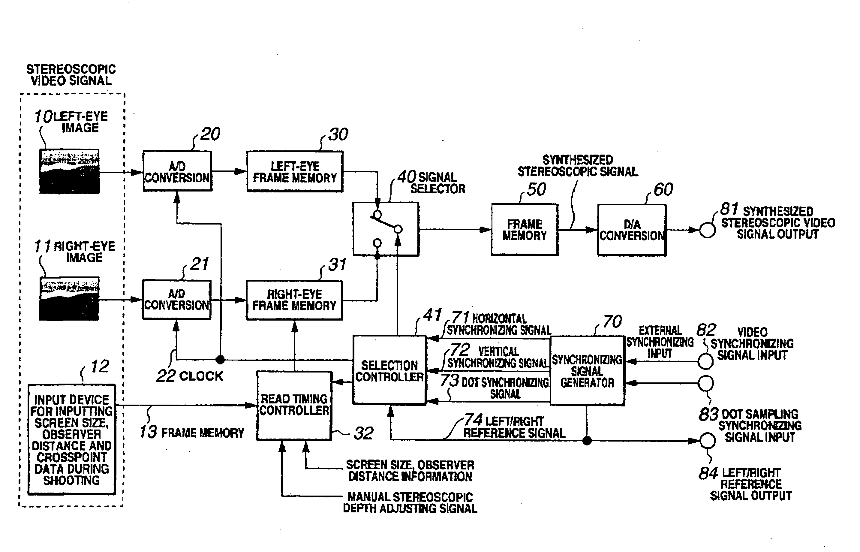
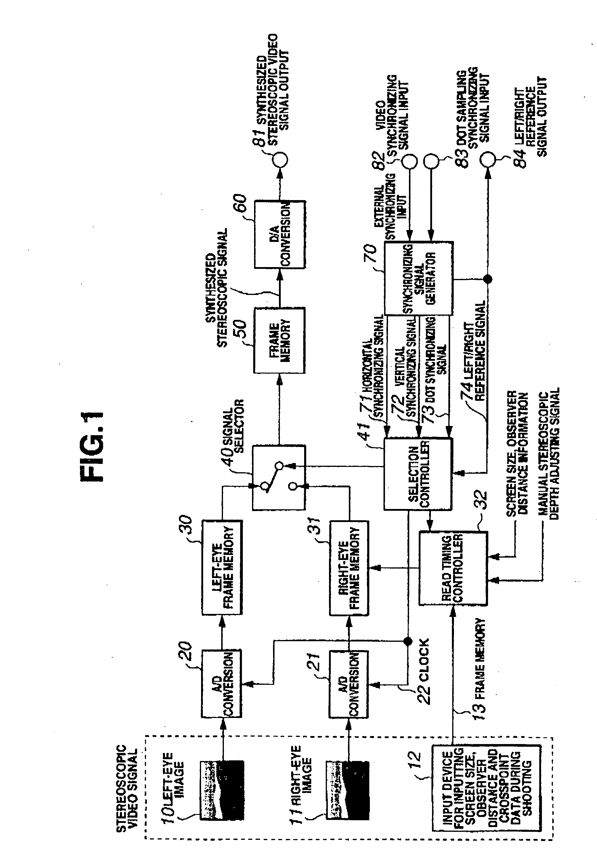
[0049]FIG. 1 is a block diagram showing the configuration of a stereoscopic video signal generation circuit according to one embodiment of this invention.

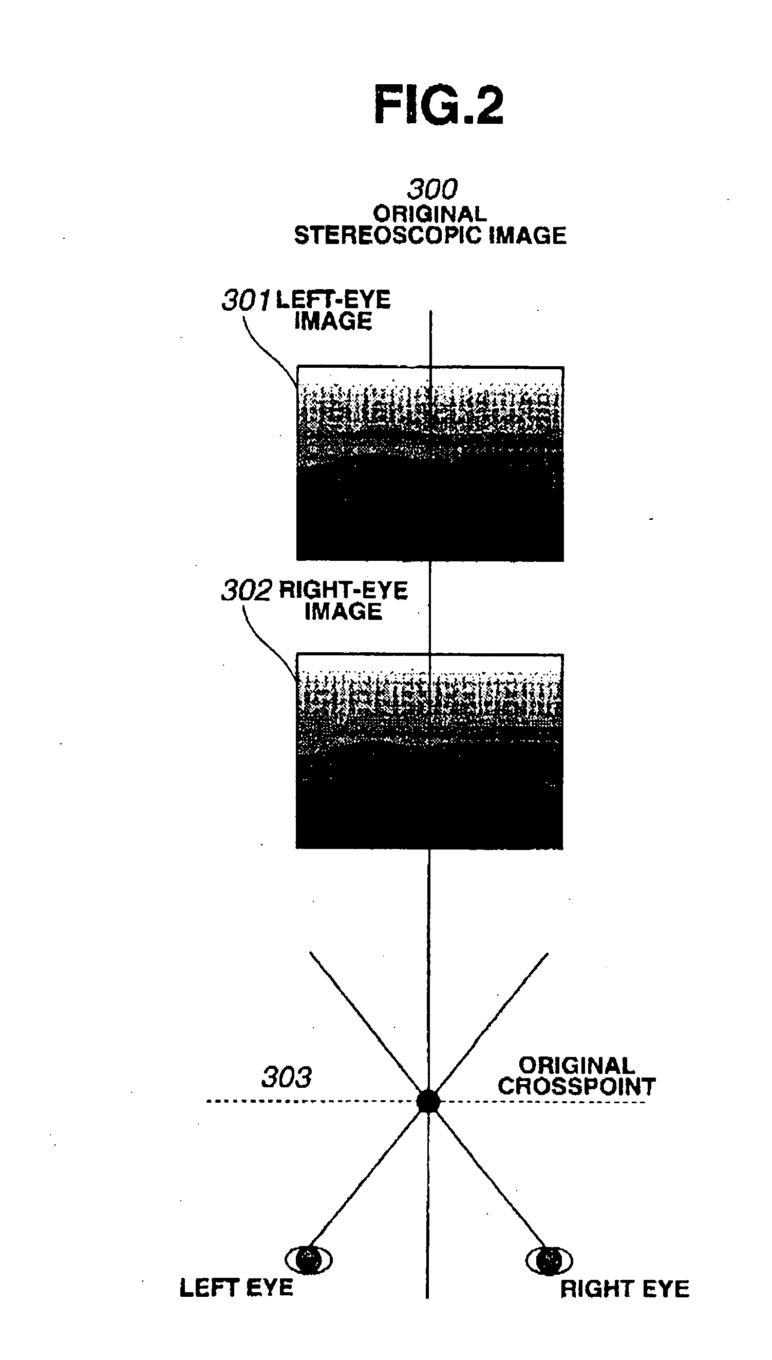
[0050] The stereoscopic video signal generation circuit according to one embodiment of this invention receives, as data recorded during shooting, a left-eye image 10, a right-eye image 11, and a distance to crosspoint (CP information) 13. The left-eye image 10 is shot by a left-eye camera and the right-eye image 11 by a right-eye camera arranged side by side with the left-eye camera. The left-eye camera and the right-eye camera are inclined toward each other, i.e., they are shifted from their parallel positions where their optical axes are parallel, so that their optical axes cross each other. A point where the cameras' optical axes cross is a crosspoint (CP) located on an object plane. During shooting, the camera equipment mea...


PUM


Abstract

A three-dimensional display is provided which can produce a stereoscopic image with a natural stereoscopic depth even on different screen sizes. A stereoscopic video signal generation circuit, which supplies a stereoscopic video signal to the three-dimensional display that forms a stereoscopic image by taking advantage of binocular disparity parallax, comprises: an information retrieving means for retrieving video information on the stereoscopic image and display information on the three-dimensional display; and an offset setting means for offsetting a left-eye image and a right-eye image relative to each other according to the video information and the display information to adjust the stereoscopic depth of the image displayed.

Description

BACKGROUND OF THE INVENTION [0001] 1. Field of the Invention [0002] The present invention relates to a display and more specifically to a stereoscopic video signal generation circuit capable of changing a depth of a stereoscopic image according to a display screen size. The invention also relates to a three-dimensional display incorporating the stereoscopic video signal generation circuit. [0003] 2. Description of the Prior Art [0004] A conventional method of shooting a stereoscopic image of a subject, as described in Japanese Patent Disclosure No. 2001-231055, uses two cameras, a first camera for a right-eye image and a second camera for a left-eye image. An optical axis of the first camera and an optical axis of the second camera are made to cross each other at a crosspoint or convergence point CP on a subject plane. A technique has been proposed which measures a distance from the camera equipment to the subject plane (i.e., distance to the CP). [0005] However, if the distance to ...

Claims


Application Information

Patent Timeline
IPC IPC(8): H04N13/04H04N13/00H04N15/00H04N13/122H04N13/128
CPCH04N13/0018H04N13/0022H04N13/0425H04N13/0497H04N13/122H04N13/128H04N13/327H04N13/398
Inventor TOMITA, SEIJIRO
Owner TOMITA SEIJIRO
Learn More