
Vehicle remote control interface for controlling multiple electronic devices

a technology for remote control and electronic devices, applied in the field of remote control interfaces, can solve the problems of unfavorable passengers' safety belts to control electronic devices, and achieve the effect of convenient control of multiple electronic devices

Inactive Publication Date: 2006-09-07
AAMP OF FLORIDA
View PDF39 Cites 15 Cited by
  • Summary
  • Abstract
  • Description
  • Claims
  • Application Information

AI Technical Summary

Benefits of technology

[0017] The aforementioned needs are satisfied by the multi-unit interface system described hereinbelow. In one aspect the multi-unit interface comprises at least two electronic devices, at least one control located remotely from the at least two electronic devices, and a remote interface circuit coupling the at least two electronic devices to the at least one control. As such, the remote interface circuit allows a user to alternatively control the at least two electronic devices. Advantageously, the user can conveniently control multiple electronic devices without having to reach for the actual electronic device.
[0018] This promotes convenience and safety because the driver will not have to remove a hand from the steering wheel in order to control the electronic device, and the driver is less likely to be distracted from driving when doing so. Also, passengers can likely stay in their seats when controlling the electronic units making it unlikely that the passengers would unbuckle their safety belt to control the electronic unit.

Problems solved by technology

Also, passengers can likely stay in their seats when controlling the electronic units making it unlikely that the passengers would unbuckle their safety belt to control the electronic unit.

Method used


Image

  • Vehicle remote control interface for controlling multiple electronic devices
  • Vehicle remote control interface for controlling multiple electronic devices
  • Vehicle remote control interface for controlling multiple electronic devices

Examples


Embodiment Construction

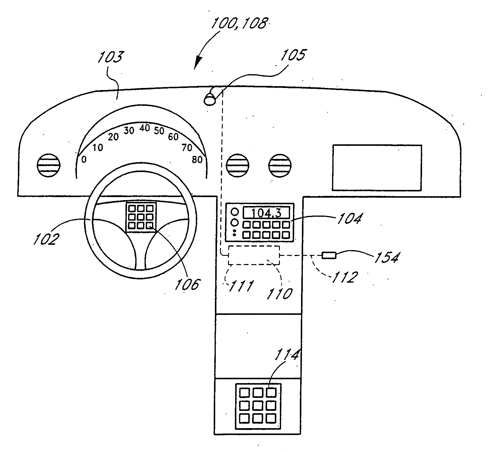
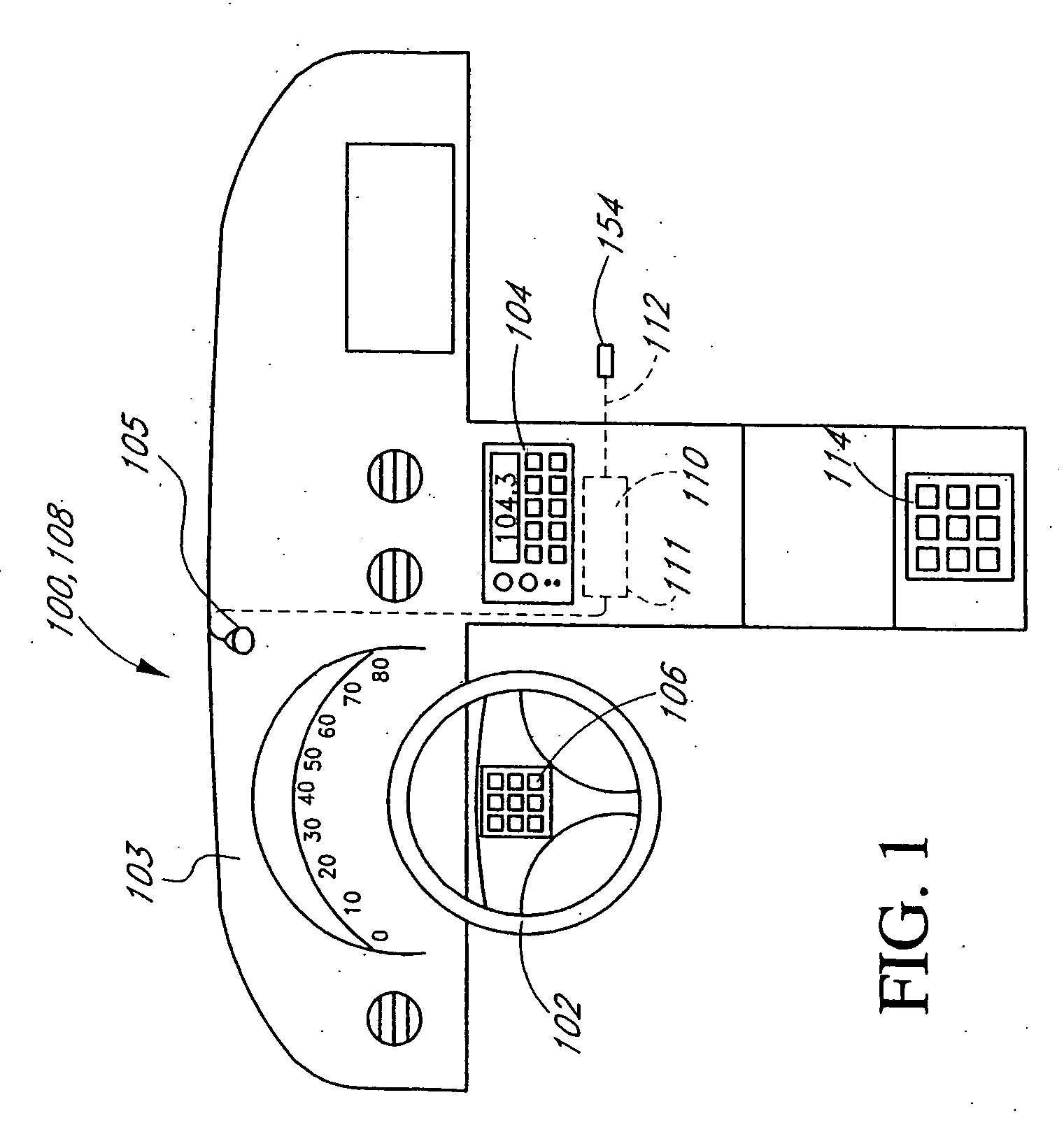
[0035] Reference will now be made to the drawings wherein like numerals refer to like parts throughout. FIG. 1 illustrates a perspective view of an exemplary vehicle interior incorporating the components of a remote stereo control interface system 100. The remote stereo control interface system 100 is comprised of factory installed local stereo controls 106 generally located in the center hub of a typical vehicle steering wheel 102. The local stereo controls 106 are used for the driver to make selections to a replacement after-market in-dash stereo 104, wherein these selections may include AM / FM, seek, volume up, volume down, play, etc.

[0036] The advantage of making these desired selections with the local stereo controls 106 is to reduce the occurrence of the driver moving his or her eyes away from the road or hands away from the steering wheel 102 when making selections at the in-dash stereo 104. Hence, the local stereo controls 106 are installed in the factory to give the driver ...


PUM

PropertyMeasurementUnit
heightaaaaaaaaaa
heightaaaaaaaaaa
lengthaaaaaaaaaa

Abstract

An interface device for interconnecting fixed controls of a vehicle to electronic devices. The interface device is capable of receiving control signals from fixed controls, such as steering wheel controls, backseat controls, handlebar controls, and the like, and then transmitting corresponding control signals to the electronic devices. In one aspect, the device is programmable such that the interface device emits signals corresponding to the same signals that would be emitted from a handheld remote control sold in conjunction with the different electronic devices. In one embodiment, the device is an interface between the fixed controls and a replacement stereo receiver. In another embodiment, the device is capable of recognizing spoken voice commands and generating corresponding IR signals in order to control the electronic devices. In still another embodiment, the device is an interface between the fixed controls and multiple electronic devices, such as an audio and video component.

Description

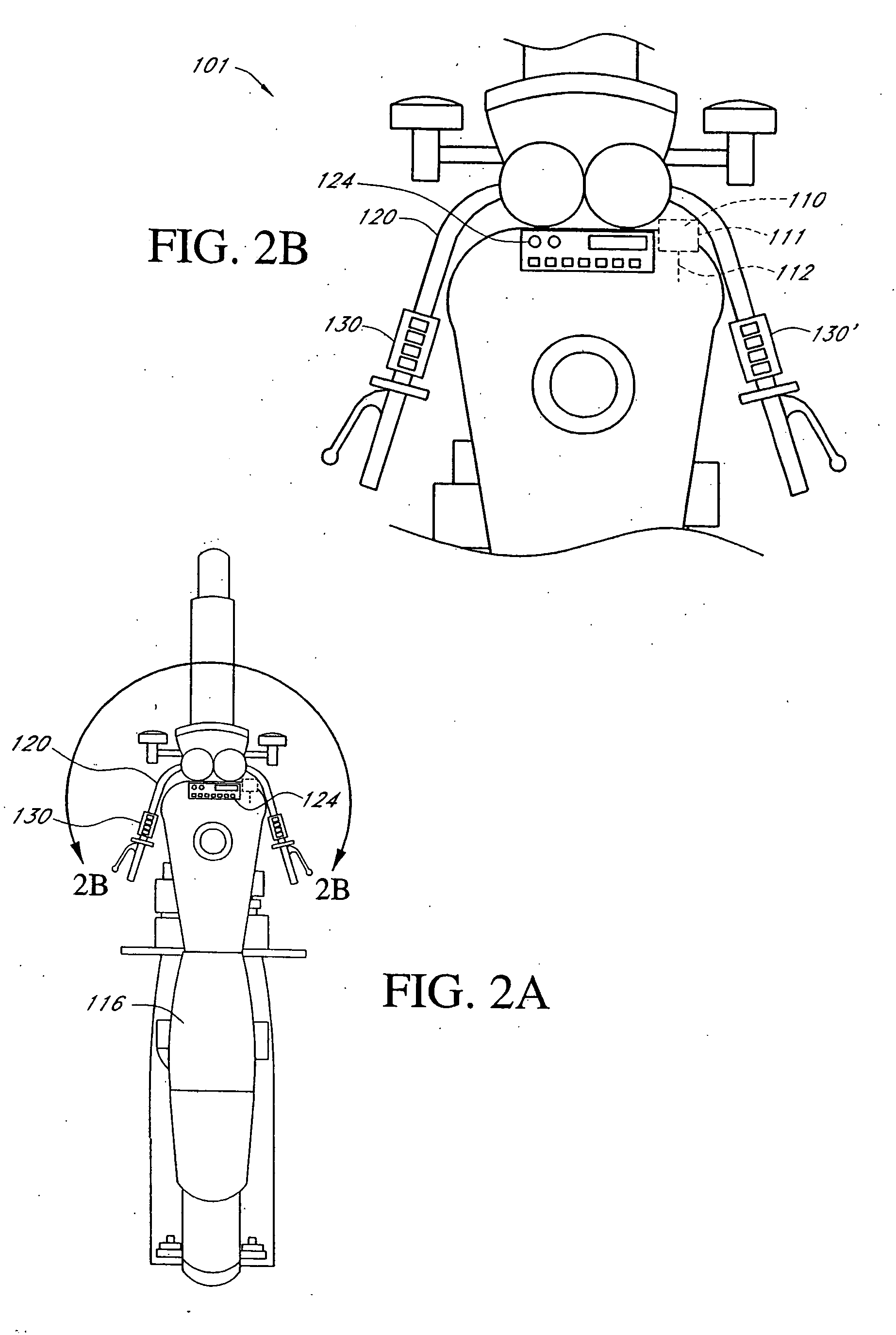
[0001] This application is a divisional of U.S. patent application Ser. No. 10 / 173,449 filed Jun. 14, 2002 which is a continuation-in-part application of U.S. patent application Ser. No. 09 / 552981 filed Apr. 21, 2000 (now U.S. Pat. No. 7,020,289) which was a continuation-in-part application of U.S. patent application Ser. No. 09 / 442,627, filed Nov. 17, 1999 (now U.S. Pat. No. 6,956,952) and claims the benefit of U.S. Provisional Application No. 60 / 108,711, filed on Nov. 17, 1998 which are hereby incorporated by reference herein their entireties.BACKGROUND OF THE INVENTION [0002] 1. Field of the Invention [0003] The present invention relates to motor vehicle accessories and, in particular, concerns a remote control interface that is configured to manage, control, and operate a plurality of audio and / or video components. [0004] 2. Description of the Related Art [0005] Motor vehicles, such as automobiles, recreational vehicles, boats, and motorcycles, are often equipped with a factory-...

Claims


Application Information

Patent Timeline
Patent Type & Authority Applications(United States)
IPC IPC(8): H04B1/00A47C31/00A47C7/62H04N7/18G11B19/02H04B1/20
CPCG11B19/027H04B1/202H04N21/41422H04N21/42204H04B1/082H04R2499/13
Inventor RIGGS, BRETT D.
Owner AAMP OF FLORIDA
Learn More