
Radiation diaphragm apparatus and radiotherapy apparatus having the diaphragm apparatus

a diaphragm and apparatus technology, applied in the field of radiotherapy apparatuses having diaphragm apparatuses, can solve the problems of heavy weight of supporting mechanism, low reliability, and difficulty in adjusting the support mechanism, and achieves smooth and reliable support of diaphragm elements, high reliability, and small size

Inactive Publication Date: 2006-09-07
TOSHIBA MEDICAL SYST CORP
View PDF20 Cites 8 Cited by
  • Summary
  • Abstract
  • Description
  • Claims
  • Application Information

AI Technical Summary

Benefits of technology

[0012] It is therefore an object of the present invention to provide a diaphragm apparatus which supports diaphragm elements smoothly and reliably and is small in size, highly reliable, and relatively inexpensive and a radiotherapy apparatus using the diaphragm apparatus.

Problems solved by technology

Therefore, its weight is heavy and the supporting mechanism requires accommodations.
However, with the conventional radiotherapy apparatus, there are the following problems.
First, with the method of supporting each diaphragm element with a grooved roller, rolling contact results in the radial direction while slide friction results in the thrust direction.
As the result, there arises a possibility that reliable accuracy may drop with time due to abrasion.
Moreover, it becomes difficult to secure space sufficient to accommodate a standard auxiliary apparatus, such as a block tray, between the radiation source and the patient as needed.
Therefore, a large number of rollers must be placed, taking up much space.
Further, assembly and adjustment also become difficult.
With the method of using grooves of V (U)-shaped cross section formed on both the sides of each diaphragm element, the structure requires a large number of parts and a large number of steps of assembly.
Thus, the cost increases.
In addition, because of rolling contact, the driving power is low and looseness is liable to occur.

Method used


Image

  • Radiation diaphragm apparatus and radiotherapy apparatus having the diaphragm apparatus
  • Radiation diaphragm apparatus and radiotherapy apparatus having the diaphragm apparatus
  • Radiation diaphragm apparatus and radiotherapy apparatus having the diaphragm apparatus

Examples


second embodiment

[0066] A second embodiment of the present invention will be described next. In this embodiment, the diaphragm unit 14 is configured such that the surface member 146A (146B) can be rotated about the shaft 145A (145B).

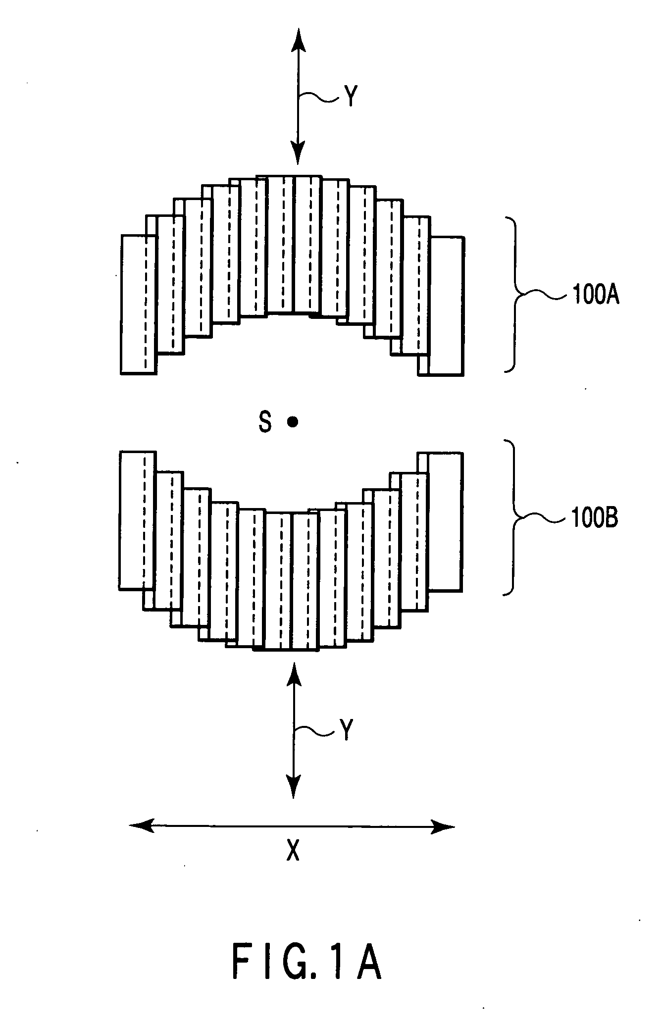
[0067]FIG. 13 is a diagram for use in explanation of the surface member 146A (146B) and the shaft 145A (145B) in the diaphragm unit of this embodiment. As shown, the surface member 146A (146B) is adapted to be rotatable about the shaft 145A (145B). The second diaphragm element 141Ak (141Bk) is in contact with the surface member 146A (146B) in the peripheral portion of the elongated hole L and supported at the point of contact by the surface member 146A (146B). Therefore, when the diaphragm element 141Ak (141Bk) moves in the radial direction (the X-direction), the surface member 146A (146B) moves inside the elongated hole L while rotating about the shaft 145A (145B) and changing the point of contact with the diaphragm element.

[0068] Such a rotating mechanism using the s...


PUM


Abstract

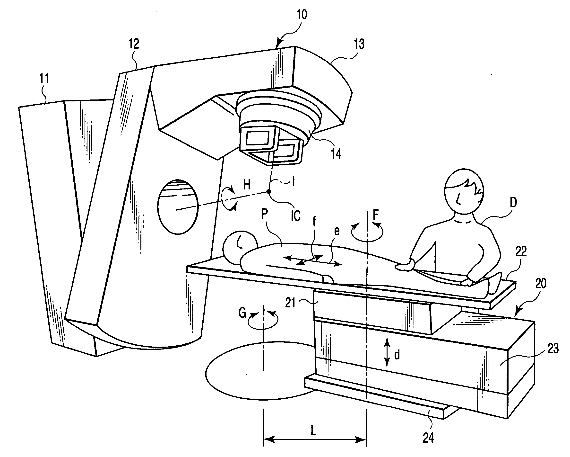
A radiation diaphragm apparatus, which is adapted to form a radiation field which is an exposed area of an object to be examined to radiation from a radiation source, comprises a plurality of diaphragm elements which are closely arranged in a first direction and movable along a second direction substantially normal to the first direction and each of which has a hole of a given shape formed to penetrate through it in the first direction, a shaft penetrating through the hole of each of the diaphragm elements, and a wear-resistant surface member coating the shaft. The shaft supports each of the diaphragm elements at a point of contact with the periphery of the hole. The diaphragm elements moves along the second direction with support by the shaft.

Description

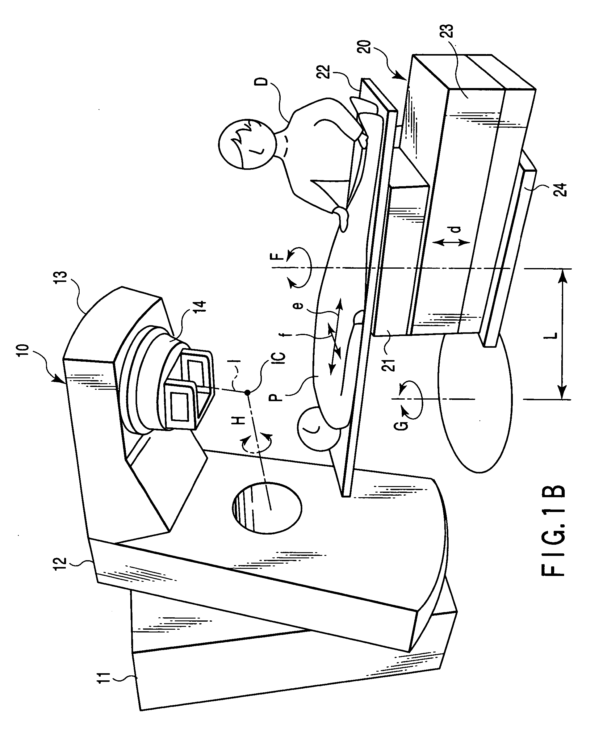
CROSS-REFERENCE TO RELATED APPLICATIONS [0001] This application is based upon and claims the benefit of priority from prior Japanese Patent Applications No. 2005-061599, filed Mar. 4, 2005; and No. 2006-023577, filed Jan. 31, 2006, the entire contents of both of which are incorporated herein by reference. BACKGROUND OF THE INVENTION [0002] 1. Field of the Invention [0003] The present invention relates to a radiation diaphragm (stop) apparatus for accurately forming a radiation field which is an area to be exposed to radiation for use in apparatus adapted for radiotherapy or radiation-based nondestructive inspection and a radiotherapy apparatus equipped with the radiation diaphragm apparatus. [0004] 2. Description of the Related Art [0005] The radiotherapy apparatus is one which irradiates a given region containing a diseased part with ionizing radiation to destroy diseased tissues, thereby allowing treatment of the diseased part. Treatments using this apparatus include postoperation...

Claims


Application Information

Patent Timeline
IPC IPC(8): A61B6/00G01N23/00G21K1/12H05G1/60
CPCA61N5/10G21K1/04G21K1/046
Inventor NOGUCHI, TADASHI
Owner TOSHIBA MEDICAL SYST CORP
Learn More