
High-speed readout circuit and system incorporating same

a high-speed readout and readout circuit technology, applied in the field ofsignal processing, can solve the problems of limited dynamic range, impractical wide-bandwidth circuit approach, and severe compromise of ladar system imaging capabilities in accuracy and range resolution, and achieve the effects of minimizing digital noise interference, minimizing noise interference, and introducing new designs

Active Publication Date: 2006-09-07
RAYTHEON CO
View PDF5 Cites 18 Cited by
  • Summary
  • Abstract
  • Description
  • Claims
  • Application Information

AI Technical Summary

Benefits of technology

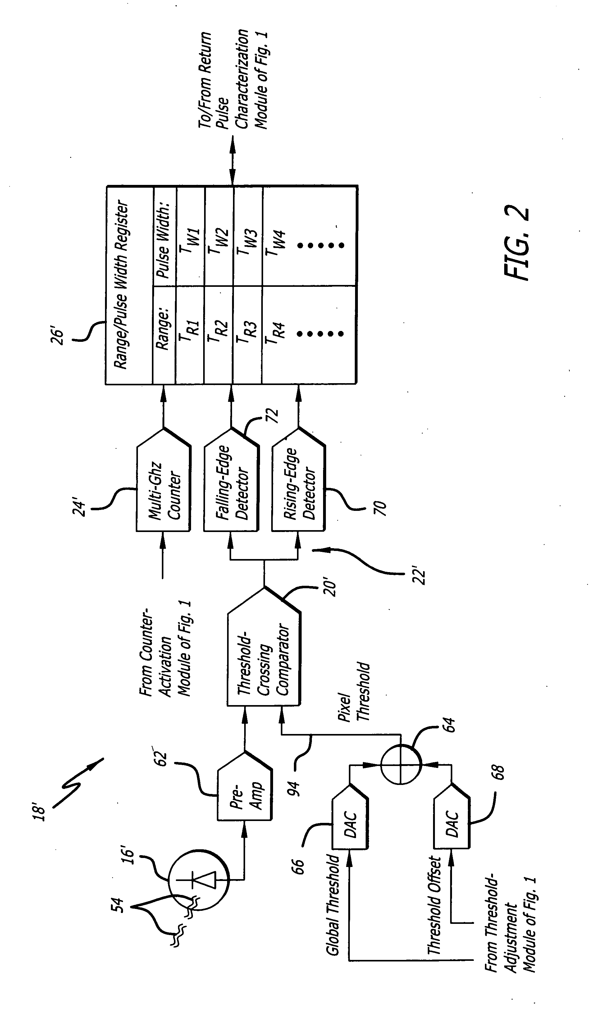
The present invention is a readout system for receiving return signals from an energy pulse in a ladar application. The system includes a mechanism for detecting energy from a scene and providing a first signal. A second mechanism times the rising and falling edges of a pulse in the first signal and provides a second signal. A third mechanism determines the characteristics of the pulse based on the second signal and generates an image of the scene. A fourth mechanism generates an image based on the characteristics. The system also includes a mechanism for selectively adjusting thresholds for each photodetector in the array of photodetectors. The invention uses rising and falling pulse edges to provide a digital signal from which pulse-intensity, pulse-width, and pulse-centroid information can be extracted. This allows for the use of broadband ladar readout circuits that can measure multiple returns from a single fired laser pulse while maintaining data integrity and minimizing digital noise interference with the analog signal output from the photodetector.

Problems solved by technology

Efficient high-bandwidth readout circuits are particularly important in three-dimensional (3-D) flash ladar applications, where low bandwidth severely compromises ladar system imaging capabilities both in accuracy and range resolution.
This approach is often impractical for wide-bandwidth circuits, which often have limited dynamic range due to raised noise floor and low power-supply voltage.
Unfortunately, this method also provides limited dynamic range.
These sample-and-hold circuits are typically undesirably large and have low bandwidth, which limits sampling rate.
Image range depth is compromised accordingly.
Analog sample-and-hold readout circuit components often limit data transfer frame rates to between 30-60 Hz, which is undesirably slow.
However, current ROIC's employing sample-and-hold methods cannot accommodate sufficient storage capacitors to effectively accommodate such high sampling rates.
However, such systems often ignore valuable information contained in subsequent returns.
Existing ROIC's have difficulty achieving high bandwidth, high sampling rate, and detecting multiple returns per pixel.
To receive and analyze multiple returns using conventional sample-and-hold technology would require an impractical number of sample-and-hold circuits.
However, analog circuitry for measuring pulse intensity and centroid is often bulky and consumes excess power.
However, use of intense narrow pulses requires a wider bandwidth, which increases the noise floor, resulting in reduced dynamic range and pulse clipping.
Consequently, intensity information and pulse-centroid information contained in these returns is lost, since conventional ladar systems often require the full pulse to accurately determine pulse centroid and intensity.
Clipping is particularly problematic in systems requiring pulse-intensity and centroid information for accurate target detection and tracking.
Conventional ROIC's often lack sufficient bandwidth to accommodate very narrow and / or high frequency pulses, which are often required for optimal image resolution.
Conventional 3-D flash ladar sensors often employ ROIC's that cannot accommodate multiple returns and have limited frame rates between 30-60 Hz due to hardware and system design constraints.
However, as system bandwidth increases, dynamic range often decreases, resulting in lost intensity information.

Method used


Image

  • High-speed readout circuit and system incorporating same
  • High-speed readout circuit and system incorporating same
  • High-speed readout circuit and system incorporating same

Examples


Embodiment Construction

[0025] While the present invention is described herein with reference to illustrative embodiments for particular applications, it should be understood that the invention is not limited thereto. Those having ordinary skill in the art and access to the teachings provided herein will recognize additional modifications, applications, and embodiments within the scope thereof and additional fields in which the present invention would be of significant utility.

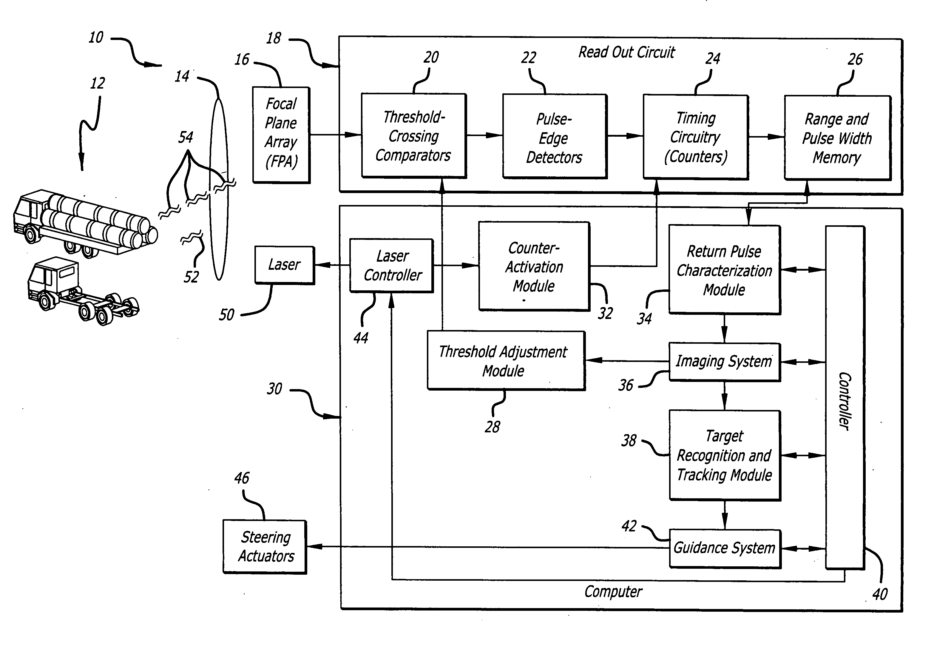
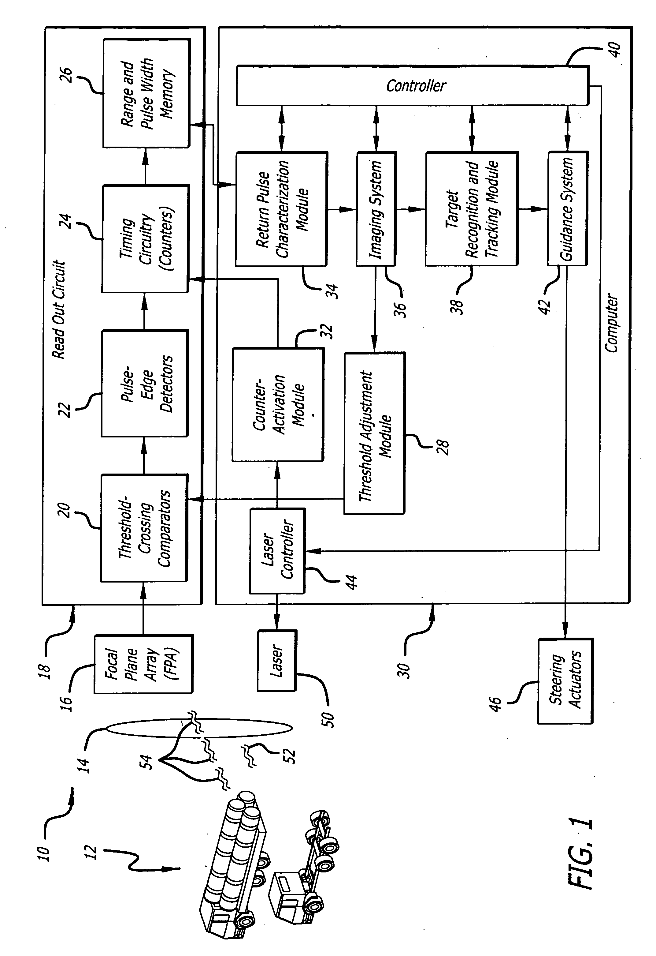
[0026]FIG. 1 is a diagram of a ladar system 10 employing a unique readout circuit 18 according to an embodiment of the present invention. For clarity, various components, such as power supplies, local oscillators, integrated circuit chips, and so on have been omitted from the figures. However, those skilled in the art with access to the present teachings will know which components to implement and how to implement them to meet the needs of a given application.

[0027] In the present embodiment, the system 10 is aimed at a scene 12 an...


PUM


Abstract

A readout system for receiving return signals originating from one or more energy pulses fired toward a scene. The system includes a first mechanism for detecting energy received from the scene and providing a first signal in response thereto. A second mechanism times a rising edge and a falling edge of a pulse contained in the first signal and provides a second signal in response thereto. In a specific embodiment, a third mechanism determines characteristics of the pulse based on the second signal, which include characteristics, such as pulse width, pulse intensity, and / or pulse centroid, sufficient to generate an image of the scene.

Description

FIELD OF INVENTION [0001] This invention relates to signal processing. Specifically, the present invention relates to readout circuits and accompanying systems for reading data from detectors or arrays of detectors. DESCRIPTION OF THE RELATED ART [0002] Readout circuits are employed in various demanding applications. Manned and unmanned aerial vehicles and missiles require high-accuracy and high-resolution laser radar to accomplish advanced target recognition (ATR), target under trees (TUT), obstacle avoidance, and vehicle guidance. Such systems require compact, cost-effective, high-bandwidth, and efficient readout circuits for handling data output from arrays of energy detectors. [0003] Efficient high-bandwidth readout circuits are particularly important in three-dimensional (3-D) flash ladar applications, where low bandwidth severely compromises ladar system imaging capabilities both in accuracy and range resolution. Conventionally, 3-D flash ladar systems often employ a pulsed la...

Claims


Application Information

Patent Timeline
Patent Type & Authority Applications(United States)
IPC IPC(8): G01C3/08
CPCG01C3/08
Inventor HALMOS, MAURICE J.KLARAS, LOUIS F.BULOT, JEAN-PAUL
Owner RAYTHEON CO
Learn More