
Optical communication device

Inactive Publication Date: 2006-08-31
FUJITSU LTD
View PDF6 Cites 23 Cited by
  • Summary
  • Abstract
  • Description
  • Claims
  • Application Information

AI Technical Summary

Benefits of technology

[0048] A more specific object of the present invention is to provide an optical signal transmitter and a transponder operating in a Differential Quadrature Phase Shift Keying (DQPSK) modulation scheme and capable of performing logical calculations at a low clock speed.
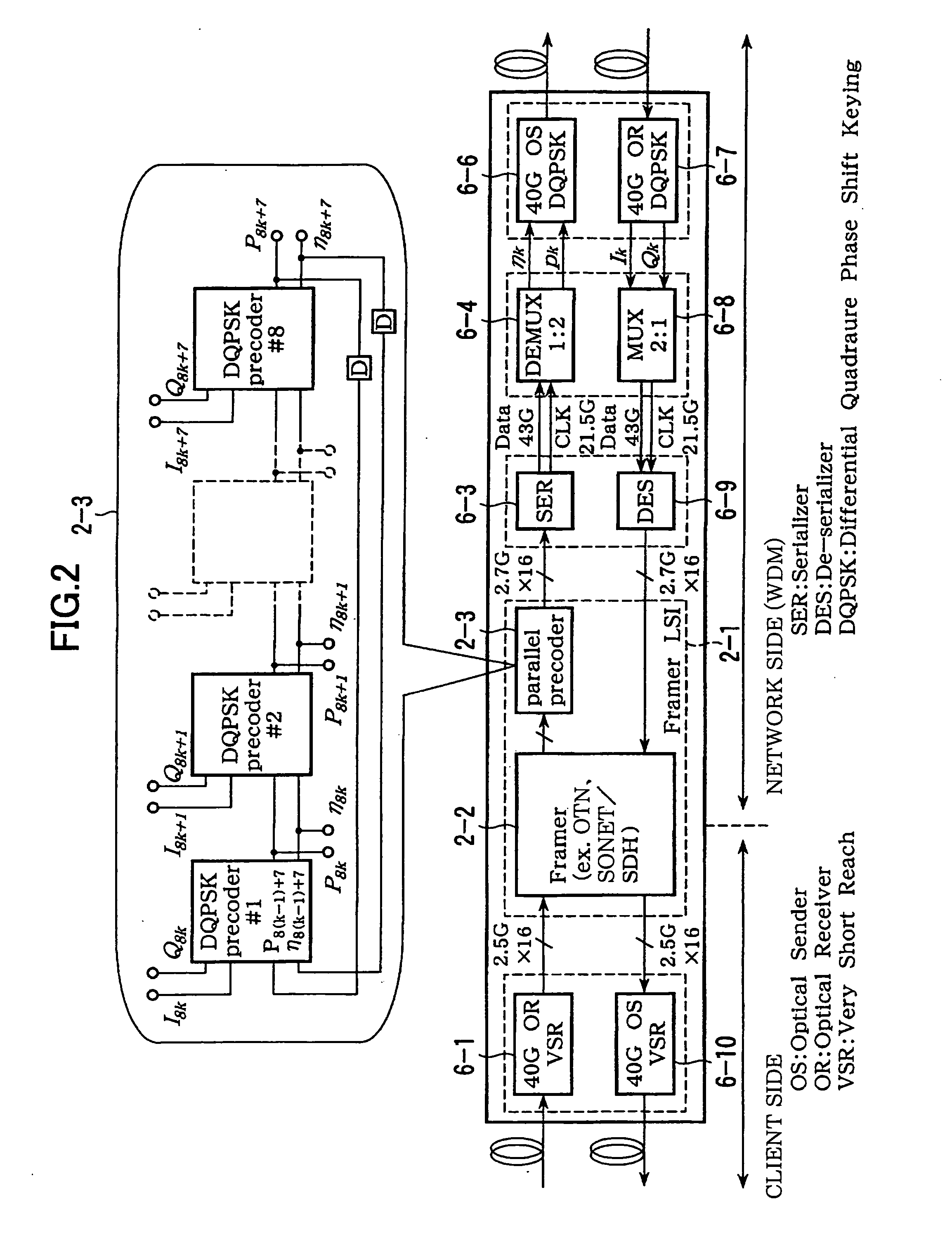
[0055] According to the present invention, because plural precoders are provided to perform preceding logical calculation in parallel, each precoder is capable of performing the logical calculation at a low speed. As a result, a high speed logical circuit for the precoder is not required, and the precoder can be formed by low speed, inexpensive and stable circuits. This is especially desirable for a precoder operating with the Differential Quadrature Phase-Shift Keying (DQPSK) modulation scheme for optical transmission at a high bit rate.
[0056] In addition, because each precoder is capable of performing the logical calculation at a low speed, if the precoders and a framer LSI for multiplexing transmission data signals for multiplexing transmission are integrated as an LSI (Large Scale Integrated circuit), the DQPSK transmitter can be constructed at low cost.

Problems solved by technology

The DQPSK precoder is not able to perform the logical calculations at a low clock speed.

Method used


Image

  • Optical communication device
  • Optical communication device
  • Optical communication device

Examples


Embodiment Construction

[0064] Below, preferred embodiments of the present invention are explained with reference to the accompanying drawings.

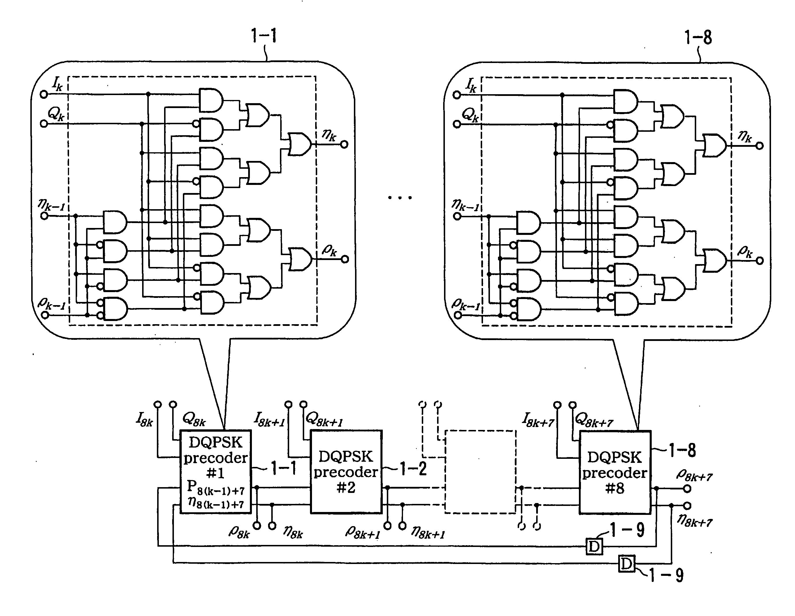
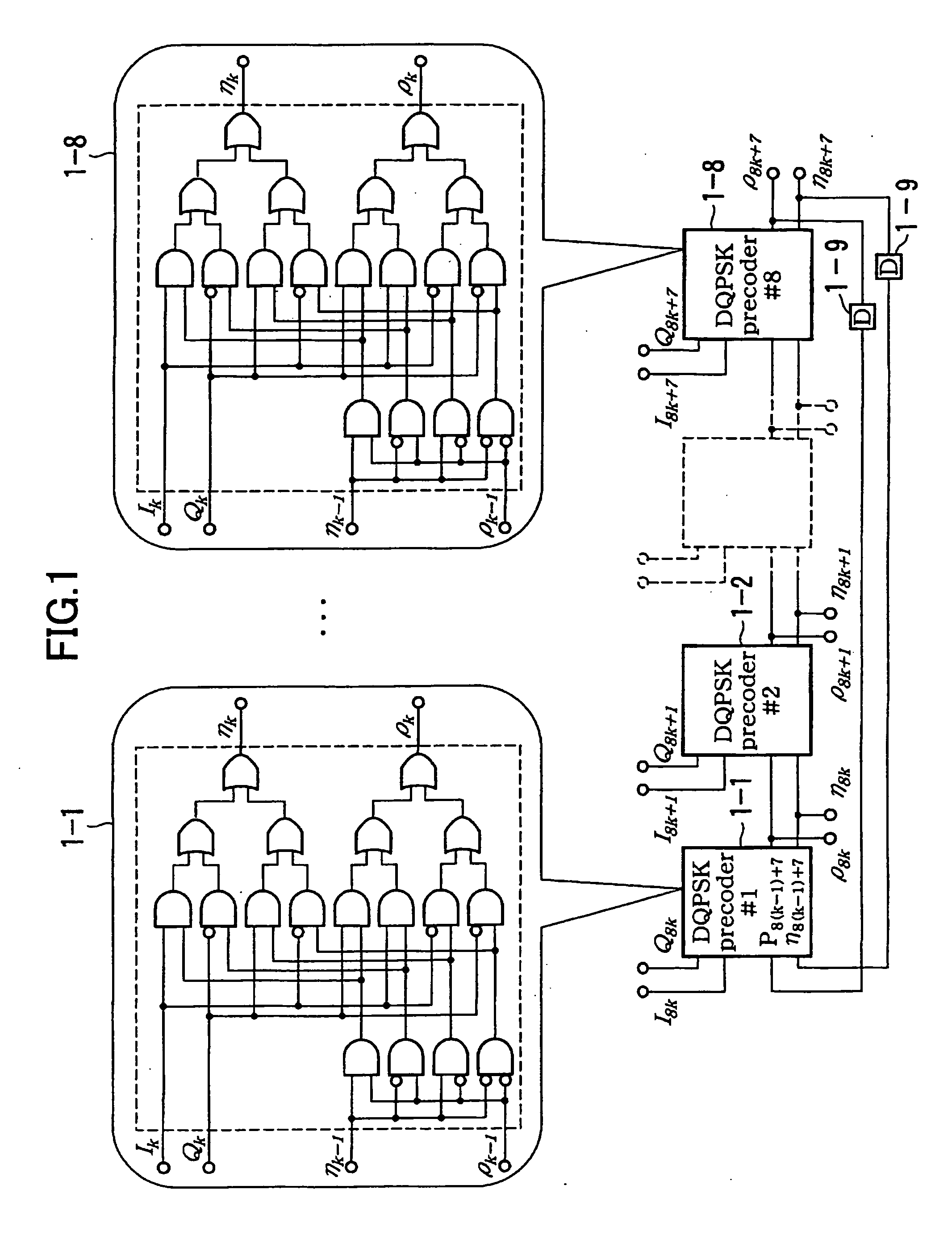
[0065]FIG. 1 is a block diagram illustrating an example of a configuration of a precoder according to an embodiment of the present invention.

[0066] In FIG. 1, there are eight aforesaid precoders arranged in parallel, and each of precoders is able to perform calculation of the logical relations (2), as described above.

[0067] The eight precoders perform the logical calculation of the logical relations (2) in one period simultaneously and in parallel on eight symbols (data signals) extracted sequentially, and perform the logical calculation in a next period on the next eight symbols (data signals) simultaneously and in parallel. This procedure is repeatedly executed.

[0068] Specifically, as illustrated in FIG. 1, there are provided a first precoder 1-1 for performing logical calculation on 8k-th data signals I8k and Q8k, a second precoder 1-2 for performing logical ...


PUM


Abstract

An optical sender is disclosed that operates in a Differential Quadrature Phase Shift Keying modulation scheme for high speed optical transmission and is capable of performing logical calculations at a low speed. The optical sender transmits a Differential Quadrature Phase Shift Keying (DQPSK) signal generated with modulation signals ρk and ηk so that a signal directly output from a signal receiver corresponding to the optical sender is in agreement with data signals Ik and Qk to be transmitted. The signal receiver is capable of modulation by DQPSK, and the modulation signals ρk and ηk are precoded by using the data signals Ik and Qk and the modulation signals one symbol earlier (ρk−1 and ηk−1) . The optical sender includes plural precoders that perform logical calculation simultaneously and in parallel on plural data signals one period after another period.

Description

BACKGROUND OF THE INVENTION [0001] 1. Field of the Invention [0002] The present invention relates to an optical sender and a transponder capable of modulation by Differential Quadrature Phase Shift Keying, particularly, to an optical sender and a transponder used in a communication system able to send and receive optical signals at a high bit rate and modulated by Differential Quadrature Phase Shift Keying (DQPSK). [0003] 2. Description of the Related Art [0004] In recent years and continuing, optical modulation schemes such as DPSK (Differential Phase Shift Keying) or DQPSK (Differential Quadrature Phase Shift Keying) are attracting attention as techniques allowing optical transmission at a bit rate higher than 40 Gbps. [0005] The DQPSK modulation scheme is superior in long distance transmission, high density multiple / large capacity transmission, and in convenience of design and usage compared to other common and well-known modulation schemes such as NRZ (Non-Return-to-Zero), CS-RZ...

Claims


Application Information

Patent Timeline
IPC IPC(8): H04L27/22H04L27/20H04B10/516H04B10/548H04B10/61
CPCH04B10/505H04B10/5051H04B10/5053H04B10/5055H04B10/5561H04L25/03343H04L27/2075H04L27/2096
Inventor KATAGIRI, TORUHOSHIDA, TAKESHITAKAHARA, TOMOONAKAMURA, KENTAROKUWATA, NAOKI
Owner FUJITSU LTD
Learn More