
Digital writing apparatus

a writing apparatus and digital technology, applied in the field of image writing apparatus, can solve the problems of aspect ratio problem and aspect ratio still not improved

Inactive Publication Date: 2006-08-17
RICOH KK
View PDF9 Cites 7 Cited by
  • Summary
  • Abstract
  • Description
  • Claims
  • Application Information

AI Technical Summary

Benefits of technology

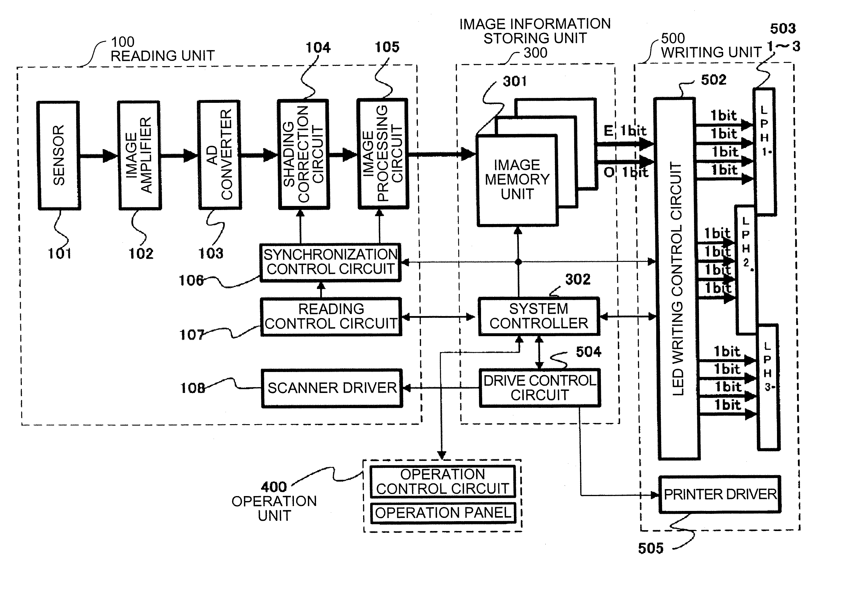
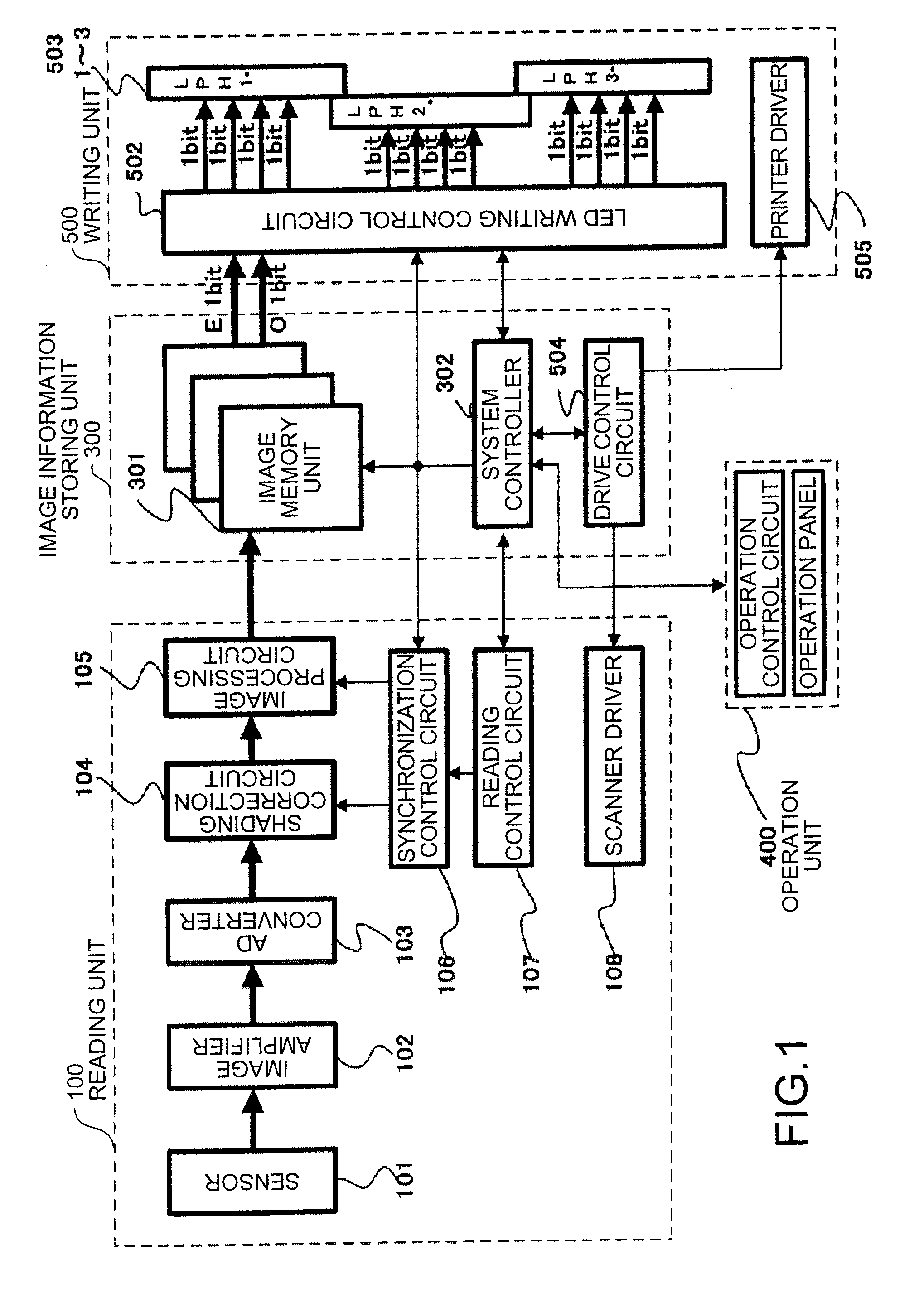
The present invention is a digital writing apparatus that solves problems in conventional technology. It includes an image forming unit that forms an image with light emitted from a light-emitting device array, and an image transfer unit that divides image data and drives each light-emitting device to perform main scanning. The array units are arranged in a sub-scanning direction and overlapped in a main scanning direction. The image transfer unit transfers divided data for a plurality of times and controls the lighting time while subjecting the image data to data processing in a period of scanning one line in the main scanning direction. The technical effects of the invention include improved image quality, faster printing speed, and reduced power consumption.

Problems solved by technology

As a result, vertical lines are printed thicker than horizontal lines to cause a problem in an aspect ratio.
However, the aspect ratio is still not improved.
Some LED light-emitting device arrays do not use the system for adding correction data and print image data.

Method used


Image

  • Digital writing apparatus
  • Digital writing apparatus
  • Digital writing apparatus

Examples


fourth embodiment

[0073] In a fourth embodiment according to the present invention, a ratio of the STRB signal and presence or absence of the data processing are related to each other. When the data processing is not performed, the STRB signal lights dots at the ratio 3, that is, 7.5%. When the data processing is performed, the STRB signal lights dots at the ratio 1, that is, 2.5%. Thus, in 5, 6, 7, 8 in FIG. 4, the STRB signal is 7.5%, 2.5%, 2.5%, and 7.5%, respectively.

[0074] According to this control, it is possible to reduce lighting of a one-dot isolated point from 10% to 7.5%, control dot power, and reduce thickness of the vertical line.

fifth embodiment

[0075] In a fifth embodiment according to the present invention, the transfer system in FIG. 4 is exactly used. In (1) and (4), the data processing is not performed and the STRB signal is at 7.5% (ratio 3). In (2) and (3), the data processing is performed and the STRB signal is at 2.5% (ratio 1). Since data and lighting time at an end are extended, an edge effect is realized. Thus, it is possible to emphasize one line, that is, a horizontal line width.

sixth embodiment

[0076] In a sixth embodiment, it is possible to switch an output mode to a copier mode and a printer mode. Thus, it is possible to faithfully realize an image in image processing in the copier mode and gradation and a line image in data processing in the printer mode. This control is control in the printer mode.

[0077]FIG. 6 is a schematic diagram for illustrating a print dot diameter and an image of one-dot cross. Even pixel data 9 is printed at the duty of 7.5%, and then, odd data

[0078] is printed at the duty of 2.5%. Since the duty is 2.5%, dot power is small. Subsequently, even pixel data 11 is printed at the duty of 2.5%.

[0079] When one-dot isolated point is recognized as a pattern, the isolated point is compared with an adjacent pixel. If data changes from “1” to “0”, printing is not performed. Finally, odd pixel data 12 is printed at the duty of 7.5%. Thus, as the dot diameter, in the vertical line, pixel data is printed only at the duty of 7.5% according to data processing ...


PUM


Abstract

In transfer of even pixel data, focusing on even-number data, only the even data is selected out of eight pixels of image data read out from a storage circuit and transferred to an LED head in a unit of four bits. Four pixel data are simply selected out of eight pixels without performing one-pixel conversion. In transfer of odd pixel data, focusing on odd data, when data is “0”, “0” is directly transferred. When data is “1”, if the previous pixel data is “1”, “1” is directly transferred, and if the previous pixel data is “0”, data is converted into “0” to be transferred.

Description

CROSS-REFERENCE TO RELATED APPLICATIONS [0001] The present document incorporates by reference the entire contents of Japanese priority document, 2005-036620 filed in Japan on Feb. 14, 2005. BACKGROUND OF THE INVENTION [0002] 1. Field of the Invention [0003] The present invention relates to an image writing apparatus that uses a light-emitting device array. [0004] 2. Description of the Related Art [0005] In an image writing apparatus that writes a latent image on a photosensitive member by irradiating light, an laser diode (LD) scanning system and a system (light-emitting-device array system) using a light-emitting-device array are used. The light-emitting-device array system uses light-emitting diodes (LED) arranged in an array. In the light-emitting-device array system, when an image forming apparatus outputs a binary image, a one-dot character is printed in an elliptical shape, which is long in a horizontal direction, depending on process conditions. In a one-dot lattice image (an...

Claims


Application Information

Patent Timeline
Patent Type & Authority Applications(United States)
IPC IPC(8): B41J2/385
CPCG03G15/043H04N1/4092
Inventor ISHIKAWA, NAOICHI
Owner RICOH KK
Learn More