Medium discharging mechanism and image forming apparatus that employs the medium discharging mechanism
a technology of discharging mechanism and medium, which is applied in the direction of thin material handling, web handling, article delivery, etc., can solve the problems of paper jam, annoying noise, and decrease and achieve the effect of improving the durability of the medium-discharging mechanism and reducing the manufacturing cos
- Summary
- Abstract
- Description
- Claims
- Application Information
AI Technical Summary
Benefits of technology
Problems solved by technology
Method used
Image
Examples
first embodiment
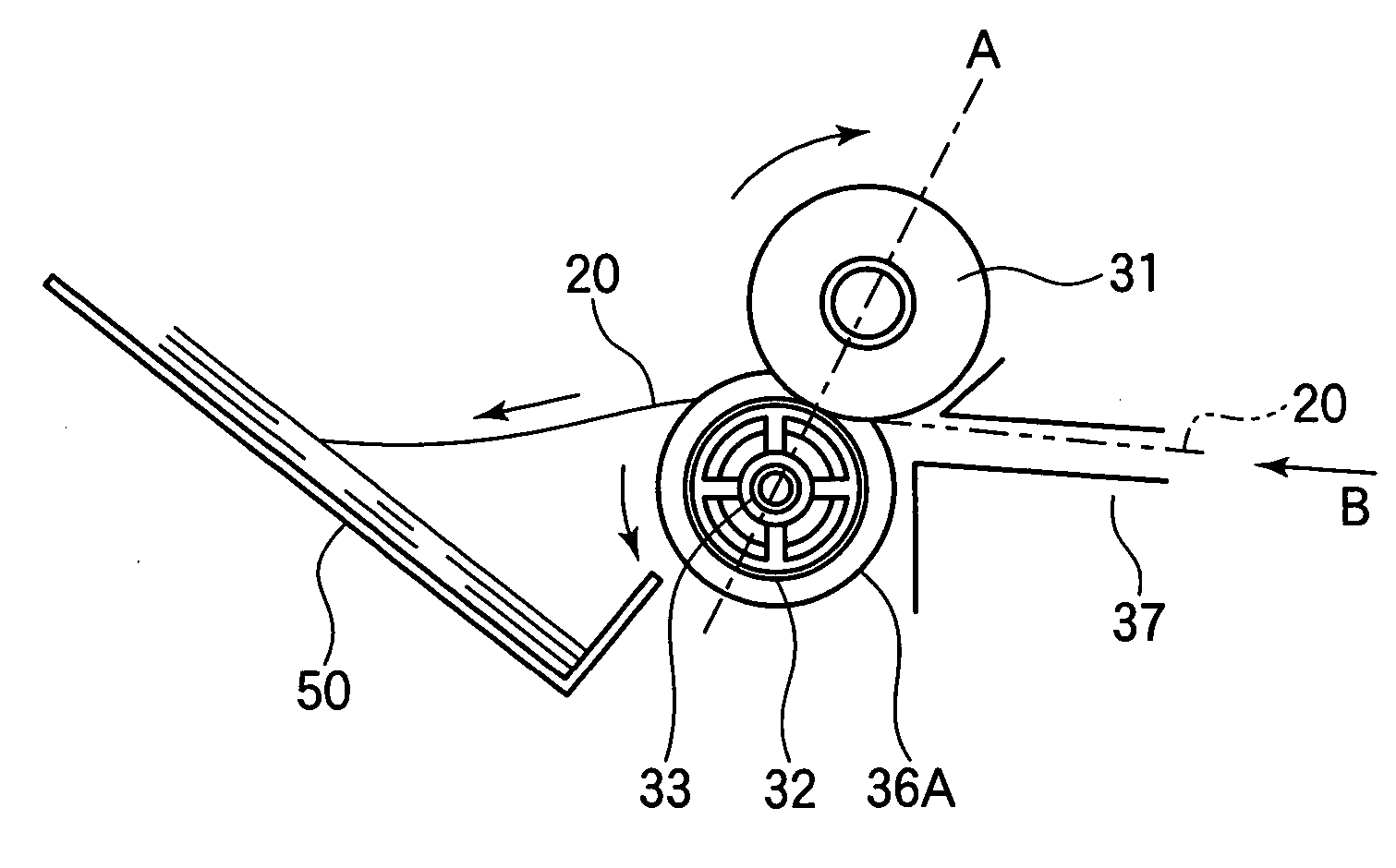
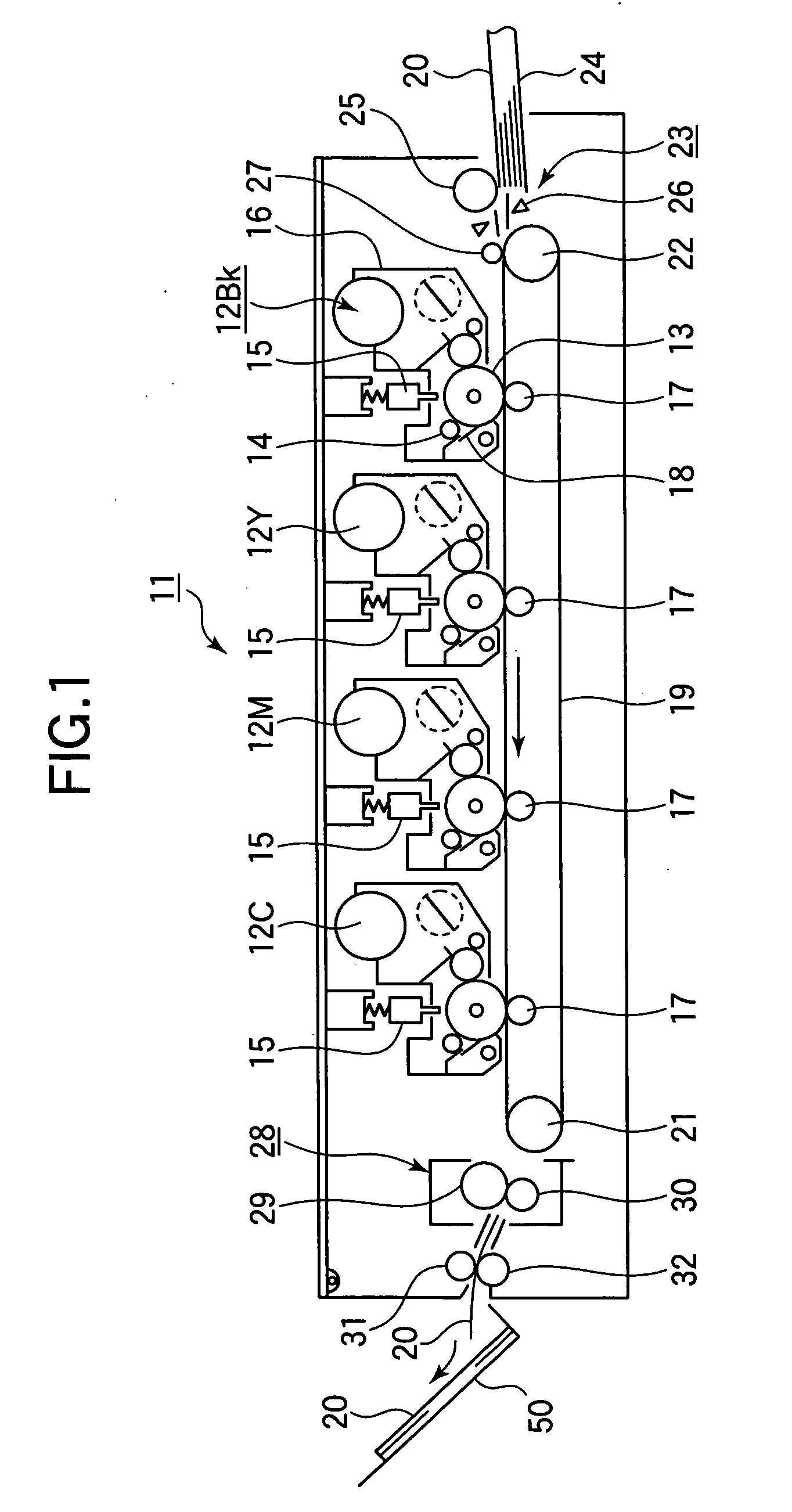
[0045]FIG. 1 is a schematic view of a printer according to a first embodiment.
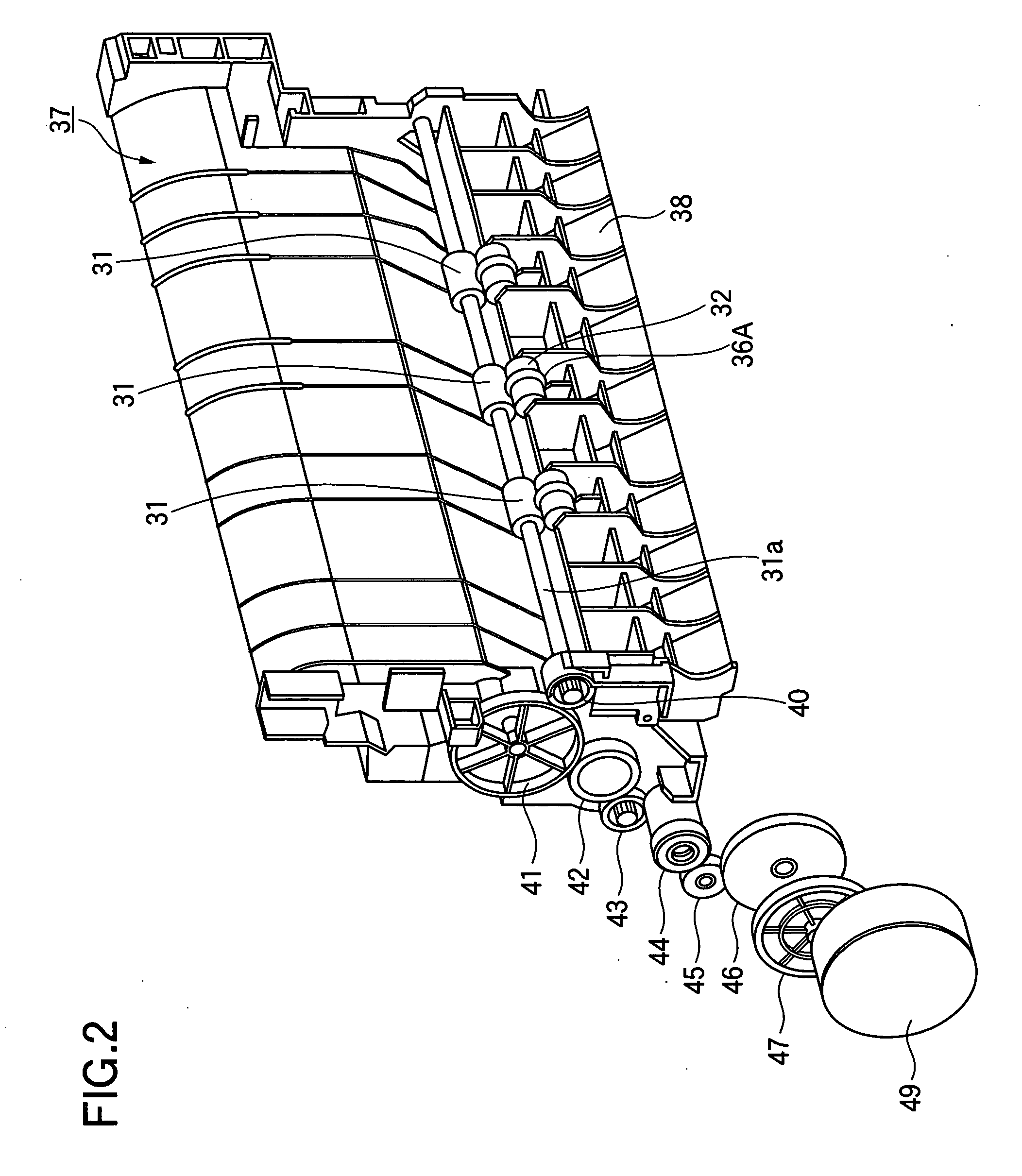
[0046]FIG. 2 is a perspective view of a medium-discharging mechanism according to the first embodiment.
[0047] Referring to FIG. 1, a printer 11 includes image forming sections 12BK, 12Y, 12M, and 12C for black, yellow, magenta, and cyan images, respectively. Each of the image-forming sections includes a photoconductive drum 13 that bears an image on it. The image-forming section further includes a charging roller 14 that charges the surface of the photoconductive drum 13, a developing unit 16, and a cleaning unit 18, which are disposed to surround the photoconductive drum 13.
[0048] An LED head 15 is disposed over the photoconductive drum 13. A transfer unit is disposed under the photoconductive drum 13. The transfer unit includes a transport belt 19 that runs in a direction in which the image-forming sections are aligned, a drive roller 21 that drives the transport belt 19 to run, a driven roller 22 tha...
second embodiment
[0076]FIG. 7 illustrates the operation of a medium-discharging mechanism according to a second embodiment.
[0077]FIG. 8 is an exploded perspective view of a pressure roller of the medium-discharging mechanism.
[0078] A resilient ring 36B according to the second embodiment has projections and recesses on its circumferential outer surface such that the projections and recesses form a wavy surface. The elements similar to those of the first embodiment have been given the same reference numerals and their description is omitted.
[0079] Referring to FIG. 7, the resilient ring 36B is formed of a resiliently deformable material such as urethane foam and has projections alternating with recesses to form a wave-shaped outer surface in a circumferential direction of the resilient ring 36B. When the outer surface of the resilient ring 36B enters the nip between the discharge roller 31 and the resilient ring 36B, the resilient ring 36B is resiliently pushed back or collapsed, and then regains i...
third embodiment
[0081] In the first and second embodiments, the pressure roller 32 is formed with a groove 32a (FIG. 5) therein to which the resilient ring 36A or 36B is fitted. A third embodiment differs from the first and second embodiments in that the pressure roller 32 is divided into two roller segments and a resilient disc 36C is assembled between the roller segments. Elements similar to those in the first and second embodiments have been given the same reference numerals and the description is omitted.
[0082]FIG. 9 is a front view illustrating a medium-discharging mechanism according to the third embodiment.
[0083] Referring to FIG. 9, a pressure roller 32 includes a roller segment 32a and a roller segment 32b. The resilient disc 36C is resiliently deformable and is sandwiched between the roller segments 32a and 32b. A shaft 33 extends through the roller segments 32a and 32b. The third embodiment eliminates the need for making a groove in the shaft 33, and thus provides an easy-to-make mecha...
PUM
 Abstract
Description
Claims
Application Information
 - R&D
- Intellectual Property
- Life Sciences
- Materials
- Tech Scout
- Unparalleled Data Quality
- Higher Quality Content
- 60% Fewer Hallucinations
Browse by: Latest US Patents, China's latest patents, Technical Efficacy Thesaurus, Application Domain, Technology Topic, Popular Technical Reports.
© 2025 PatSnap. All rights reserved.Legal|Privacy policy|Modern Slavery Act Transparency Statement|Sitemap|About US| Contact US: help@patsnap.com


