
Composite-construction treatment equipment

a technology for treating equipment and composite materials, applied in the direction of vehicle maintenance, manufacturing tools, vehicle cleaning, etc., can solve the problems of reducing durability, taking time, and requiring work, and achieves the effects of simple manner, quick and easy installation and replacement of blade holders

Inactive Publication Date: 2006-08-17
VALMET TECH INC
View PDF4 Cites 37 Cited by
  • Summary
  • Abstract
  • Description
  • Claims
  • Application Information

AI Technical Summary

Benefits of technology

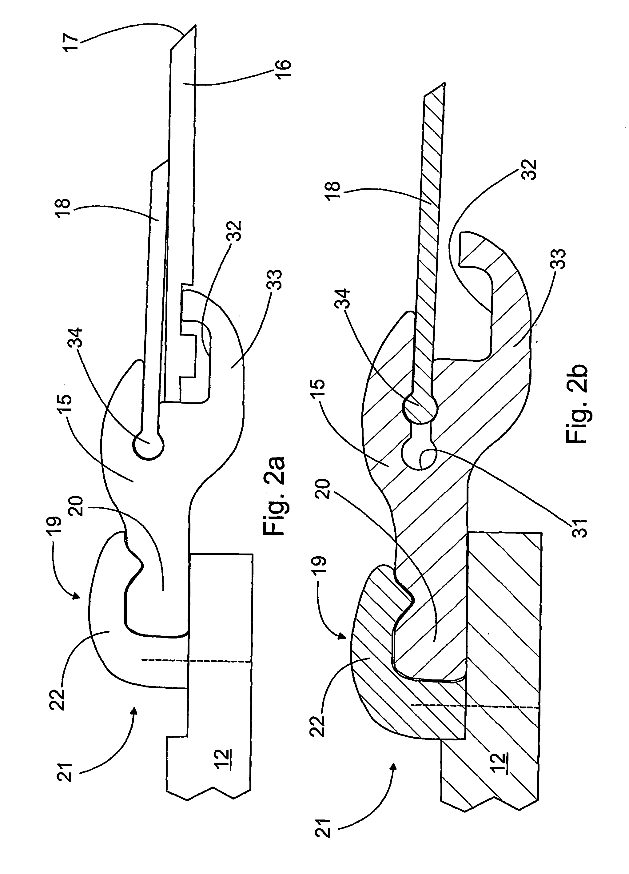
[0009] The object of this invention is to provide novel composite-construction treatment equipment, which is easier to use and service, yet more versatile than heretofore. The features characterizing this invention become evident from the appended claims. In the treatment equipment according to the invention, due to the novel design, the whole blade holder can be changed in a simple manner. This makes the installation and change of the blade holder quick and easy. Irrespective of the unexpected construction, the blade holder can additionally be provided with loading elements, for example. The blade holder can also be easily retrofitted in existing treatment equipment without major modifications. On the other hand, the design of new treatment equipment can be made simpler than before. In addition, with suitable dimensioning and design the components of the treatment equipment can be changed independent of each other, which allows to precisely adjust the treatment equipment characteristics as desired.

Problems solved by technology

This requires removing the screws during the installation and change of the blade holder, which takes time and requires working inside the paper machine.
In addition, the holes required by the screws in the arm section create discontinuity points in the blade holder construction reducing thus its durability.

Method used


Image

  • Composite-construction treatment equipment
  • Composite-construction treatment equipment
  • Composite-construction treatment equipment

Examples


Embodiment Construction

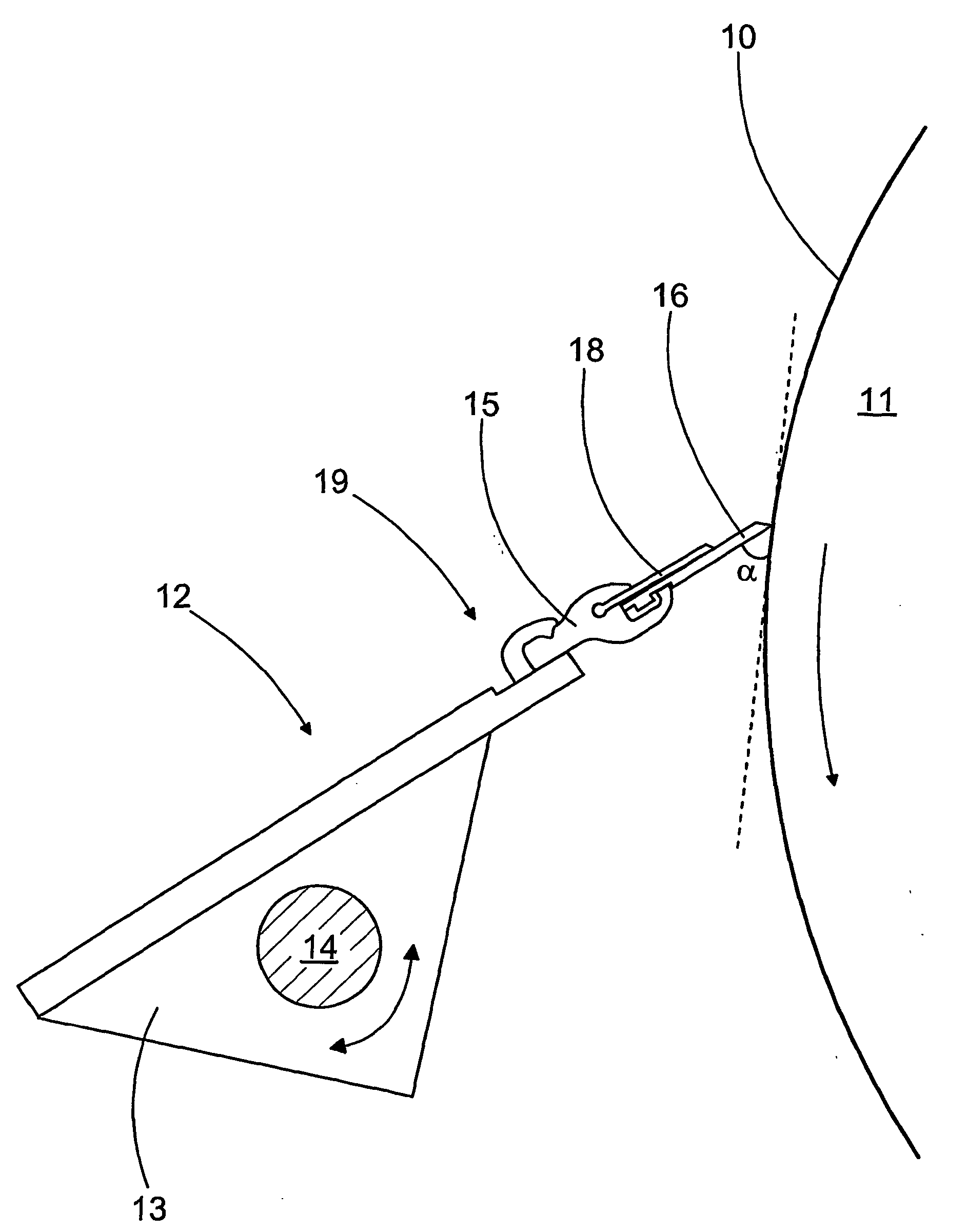
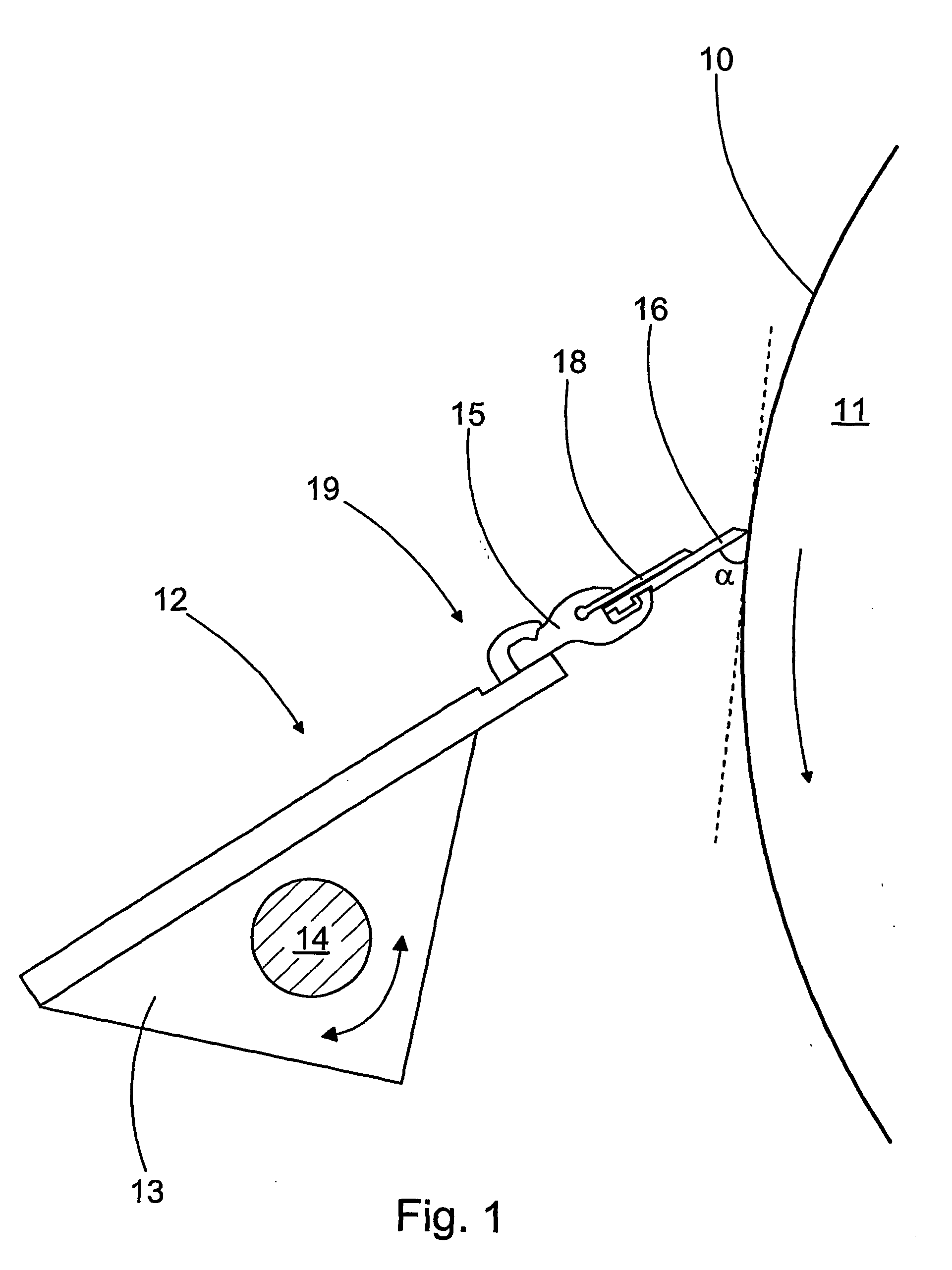
[0019]FIG. 1 shows the treatment equipment according to the invention adapted in connection with a moving surface 10. Here the moving surface 10 is a paper machine roll 11, of which only a part is shown. Generally the purpose of the treatment equipment is to treat a moving surface. In the doctoring example, the purpose of doctoring is to remove impurities from the surface or, for example, the web itself in some paper machine positions. In paper and board machines and in other forming machines, moving surfaces also comprise the surfaces of various cylinders and fabrics. The treatment equipment is used for example for web coating, in which a coating paste is applied to the surface of a moving web. This is illustrated in FIG. 5a. Furthermore, the treatment equipment comprises a frame 12, arranged in the vicinity of the surface 10 to be treated. In FIG. 1 the frame 12 is a beam 13, which is supported by a shaft 14 in a way that allows pivoting in relation to the paper machine constructi...


PUM

PropertyMeasurementUnit
Fractionaaaaaaaaaa
Angleaaaaaaaaaa

Abstract

A composite-construction treatment equipment has a frame (12) with a connected blade holder (15) made of a composite material. The blade holder (15) has a blade (16) and a separate backing blade (18). The blade holder (15) is removably adapted to the frame (12) using a pair of form-locking counter clamps (19). The form-lock is arranged tight in the lateral direction of the blade (16) and essentially free in the axial direction of the blade (16).

Description

CROSS REFERENCES TO RELATED APPLICATIONS [0001] This application is a U.S. national stage application of international app. No. PCT / FI2004 / 050006, filed Jan. 27, 2004, the disclosure of which is incorporated by reference herein, and claims priority on Finnish Application No. 20035010, filed Jan. 30, 2003. BACKGROUND OF THE INVENTION [0002] This invention relates to composite-construction treatment equipment, which is designed to be set in connection with a moving surface and which equipment includes [0003] a frame arranged in the vicinity of the said surface, [0004] a blade holder formed of a composite material as an essentially integral component and connected to the frame, [0005] a blade adapted to the blade holder, including an edge arranged to be set in contact with the moving surface by moving the blade holder, and [0006] a separate backing blade adapted to the blade holder, set to the blade holder by one end while the other end extends closer to the said edge than the blade ho...

Claims


Application Information

Patent Timeline
IPC IPC(8): D21G3/04D21H23/34D21G3/00D21H25/10
CPCD21G3/005D21H25/10B05C11/041
Inventor RATA, ILKKA
Owner VALMET TECH INC
Learn More