
Platform-specific application user interface remoting

a platform-specific application and user interface technology, applied in the execution of user interfaces, static indicating devices, instruments, etc., to achieve the effects of reducing network traffic, and enhancing memory model representation

Inactive Publication Date: 2006-08-10
NOKIA CORP
View PDF5 Cites 92 Cited by
  • Summary
  • Abstract
  • Description
  • Claims
  • Application Information

AI Technical Summary

Benefits of technology

Enables seamless adaptation of user interfaces to diverse device platforms, improving user experience, allowing manufacturer branding, and reducing network traffic and power consumption, particularly beneficial in UPnP networks.

Problems solved by technology

This may for instance be due to the fact that the server does not provide means for rendering said user interface, or because said server is part of a network in which mutual control of devices and / or data transfer between devices is desired, such as for instance in a UPnP network.

Method used


Image

  • Platform-specific application user interface remoting
  • Platform-specific application user interface remoting
  • Platform-specific application user interface remoting

Examples


third embodiment

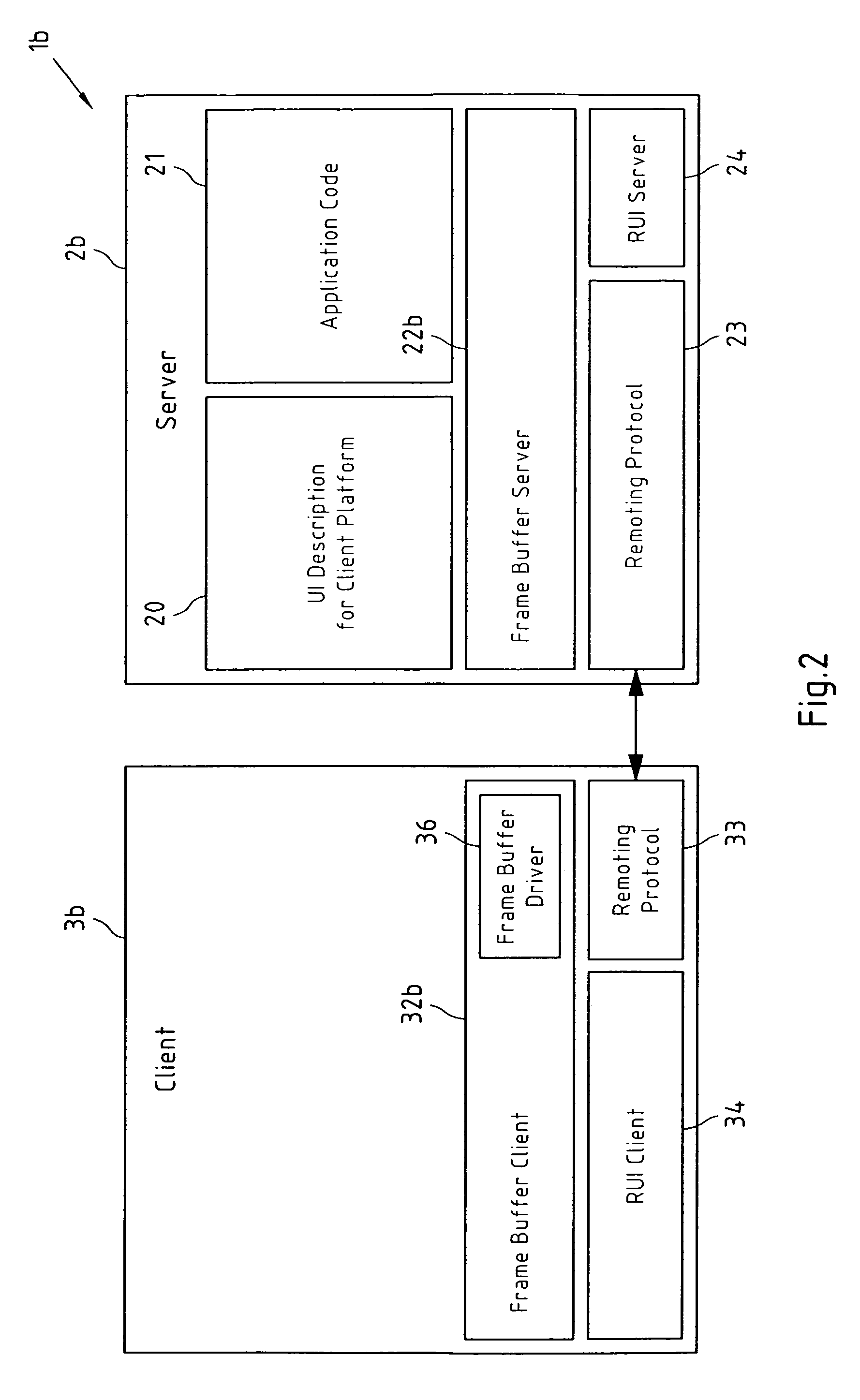
[0078]FIG. 3 depicts a block diagram of the corresponding third embodiment of a system 1c according to the present invention. System 1c comprises server 2c, and exemplarily a client 3b that equals the client 3b of the system 1b (see FIG. 2). It is readily understood that, equally well, client 3a (see FIG. 1) could have been depicted in FIG. 3 instead of client 3b, because said server 3c is capable of exporting its UI to both types of clients.

[0079] Server 2c basically has the same components as server 2a of the system 1a (see FIG. 1). However, the remote XML UI server 22a of server 2a has been extended to a remote XML UI / frame buffer server 22c. This remote XML UI / frame buffer server 22c is capable of generating both a memory model representation 26 (denoted as UIModelTree in FIG. 3) and a frame buffer representation of a UI for an application that is executed by said server 2c and represented by application code 21. This is accomplished by the frame buffer adapter 25, which is capa...

fourth embodiment

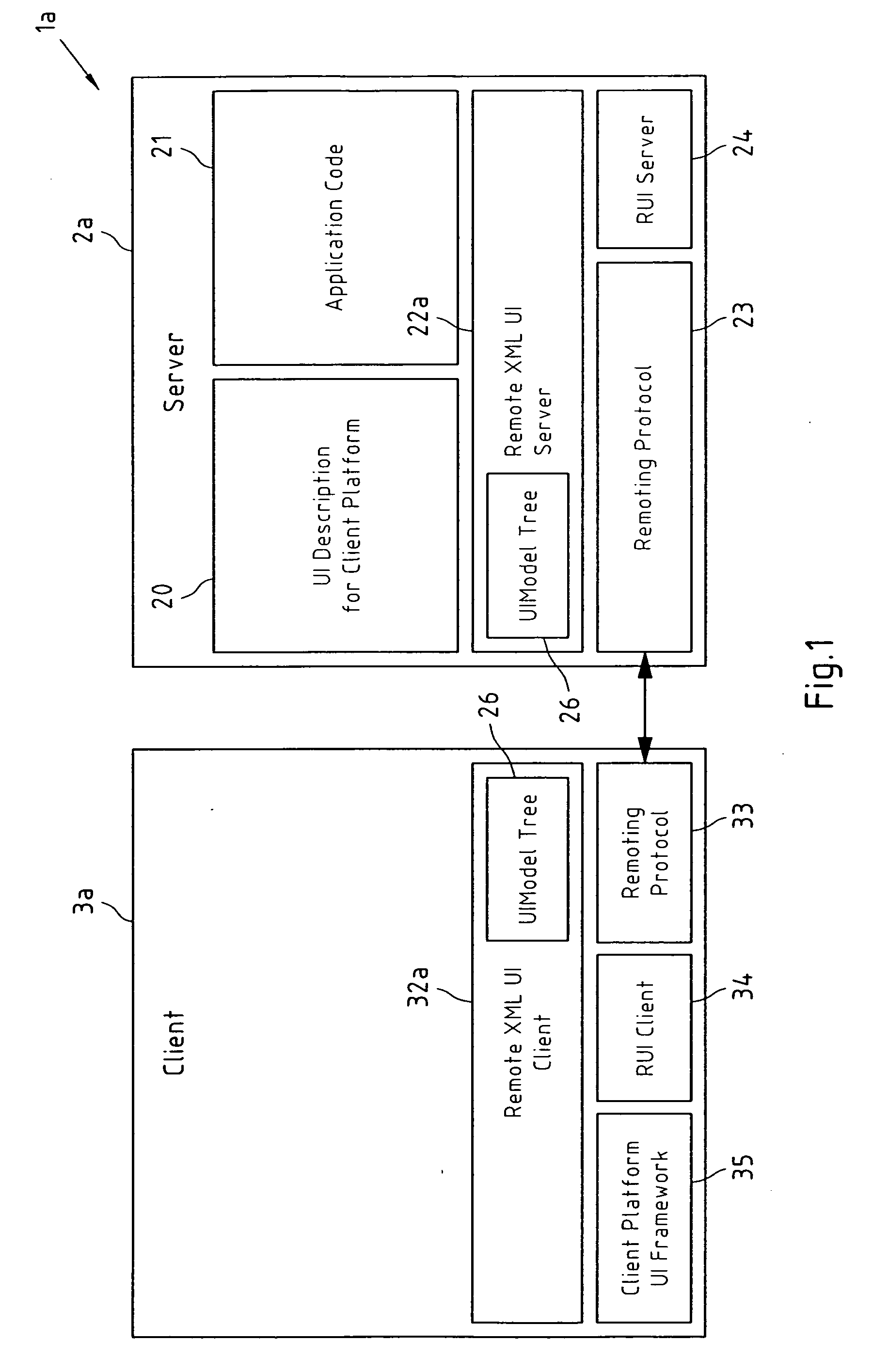
[0082]FIG. 8 depicts a block diagram of the corresponding fourth embodiment of a system 1d according to the present invention. In FIG. 8, components of the system 1d that have the same functionality as components in the system 1a of FIG. 1 are denoted by the same reference numerals. Server 2d basically has the same components as server 2a of the system 1a (see FIG. 1), and the client 3d basically has the same components as client 3a of the system 1a (see FIG. 1).

first embodiment

[0083] In contrast to the Remote XML UI server 22a, which generates the memory model representation 26 of the UI in the server 2a of system 1a according to FIG. 1, the server 2d of system 1d according to FIG. 8 comprises an enhanced Remote XML UI server 22d which generates an enhanced memory model representation 27 of the UI. This enhanced memory model representation 27 is denoted as Enhanced UIModelTree in FIG. 8. Similarly to the memory model representation 26 of the first embodiment, this enhanced memory model representation 27 is created from the platform-specific UI description 20 for a remote device platform whenever the server application needs to export the display (i.e. remote the UI) to that particular platform, but, contrary to the memory model representation 26, the enhanced memory model representation 27 does not comprise the run-time content of each UI element of the corresponding platform-specific UI description 20. Thus, it is possible, that at least one UI element (...


PUM


Abstract

This invention relates to a server-site method, a client-site method, computer program products, a client, a server, a module and a system for remoting a user interface of an application between a server that executes said application and at least one client on which a representation of said user interface is to be rendered, wherein said representation of said user interface is generated at said server under consideration of a user interface description that is specific for a device platform of said at least one client; and wherein said representation of said user interface is transferred to said at least one client. Said representation of said user interface may for instance be a memory model representation or a frame buffer representation.

Description

CROSS-REFERENCE TO RELATED APPLICATION [0001] This application is a Continuation-in-Part of U.S. patent application Ser. No. 11 / 035,424 filed on Jan. 12, 2005.FIELD OF THE INVENTION [0002] This invention relates to a server-site method, a client-site method, computer program products, a client, a server, a module and a system for remoting a user interface of an application between a server that executes said application and a client on which a representation of said user interface is to be rendered. BACKGROUND OF THE INVENTION [0003] With the addition of Device Plug and Play (PnP™) capabilities to the operating system of Personal Computers (PCs) it has become easier to set up, configure and add peripheral devices such as printers or multimedia devices to a PC. Universal Plug and Play (UpnP™) extends this simplicity to include the entire network, enabling discovery and control of devices, including networked devices and services, such as network-attached printers, Internet gateways, ...

Claims


Application Information

Patent Timeline
Patent Type & Authority Applications(United States)
IPC IPC(8): G06F15/16G06F3/00G06F17/00G06F9/00
CPCG06F3/14G06F3/1454G06F3/1462G09G2360/18G09G2370/042G06F9/4445G06F9/452
Inventor STIRBU, VLAD
Owner NOKIA CORP
Learn More