
Cable alarm security device

a security device and cable technology, applied in the field of cable alarm security devices, can solve the problems of complicated mechanical mechanisms, large and bulky cable devices, and the inability to secure the eas tag of merchandise, and achieve the effect of easy removal

Inactive Publication Date: 2006-08-03
CHECKPOINT SYST INC
View PDF46 Cites 69 Cited by
  • Summary
  • Abstract
  • Description
  • Claims
  • Application Information

AI Technical Summary

Benefits of technology

The present invention is a cable alarm security device that can be easily placed on merchandise and removed at the checkout station. It uses a flexible cable with a locking mechanism and an alarm system. The cable can be of different thicknesses and types, and can contain electrical conductors for protecting it. The alarm system includes an LED that is visible from both sides of the housing, and an EAS tag that will activate an internal alarm if the security device comes close to a security gate alarm system. The locking mechanism is magnetically actuated and can only be opened with a pair of magnets, reducing the risk of the device being opened by a single magnet. The security device is adaptable for use with various items of merchandise and can sound an audible alarm if the cable is compromised or if the security device approaches a security gate.

Problems solved by technology

Securing the EAS tag to merchandise is a problem faced by many retail establishments.
Many of these types of cable devices are large and bulky and require complicated mechanical mechanisms to lock and unlock the cable from the device for subsequent removal from the item of merchandise.
Even though the EAS tag could actuate a different alarm at a security gate upon passing through the gate, this does not always prove satisfactory due to the sensitivity of the gate which must be tuned to numerous security devices used throughout the store.
Also once the stolen item of merchandise having the security device still attached thereto leaves the store premises, the thief can easily disappear in a crowd or parking lot and the store alarm only alerts the store personnel that an item of merchandise has been stolen.

Method used


Image

  • Cable alarm security device
  • Cable alarm security device
  • Cable alarm security device

Examples


first embodiment

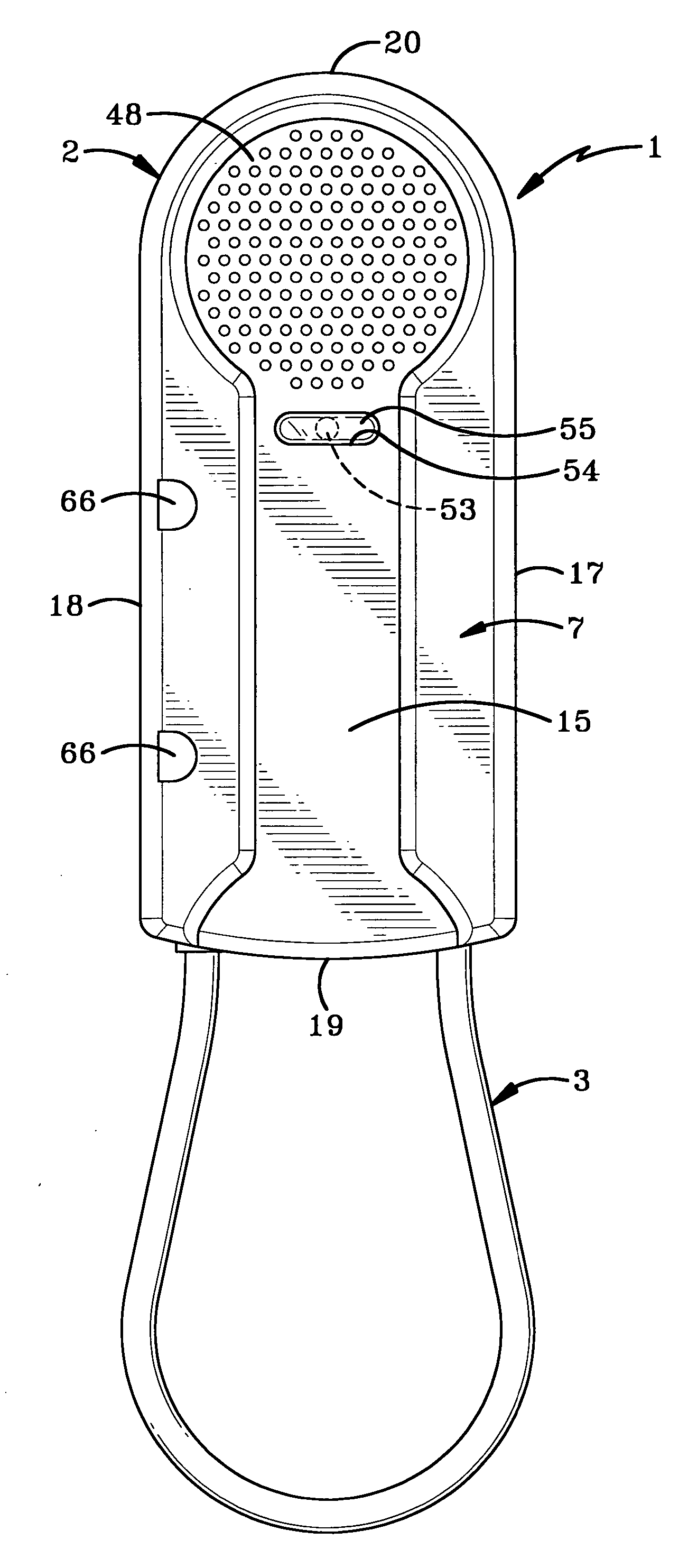
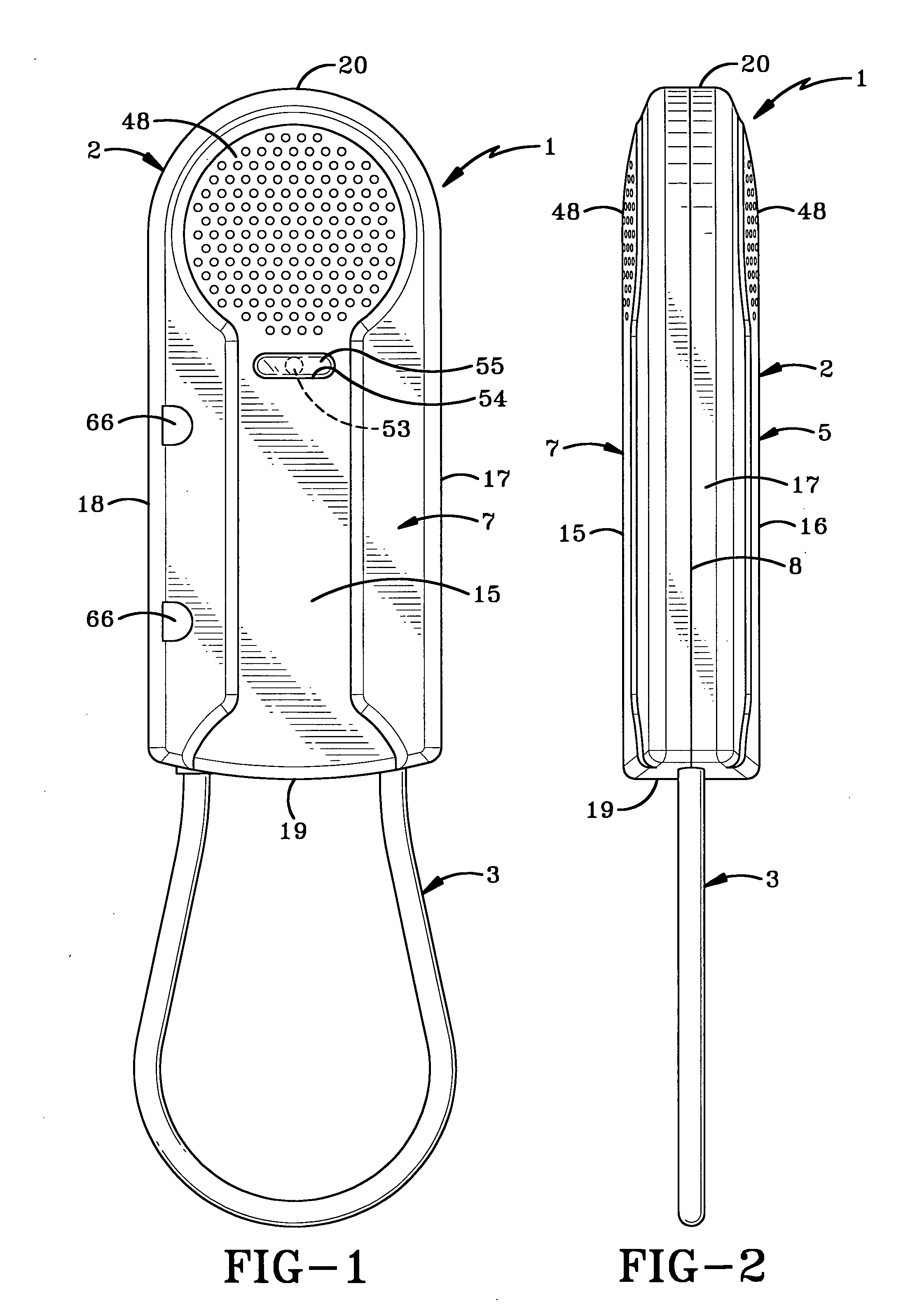
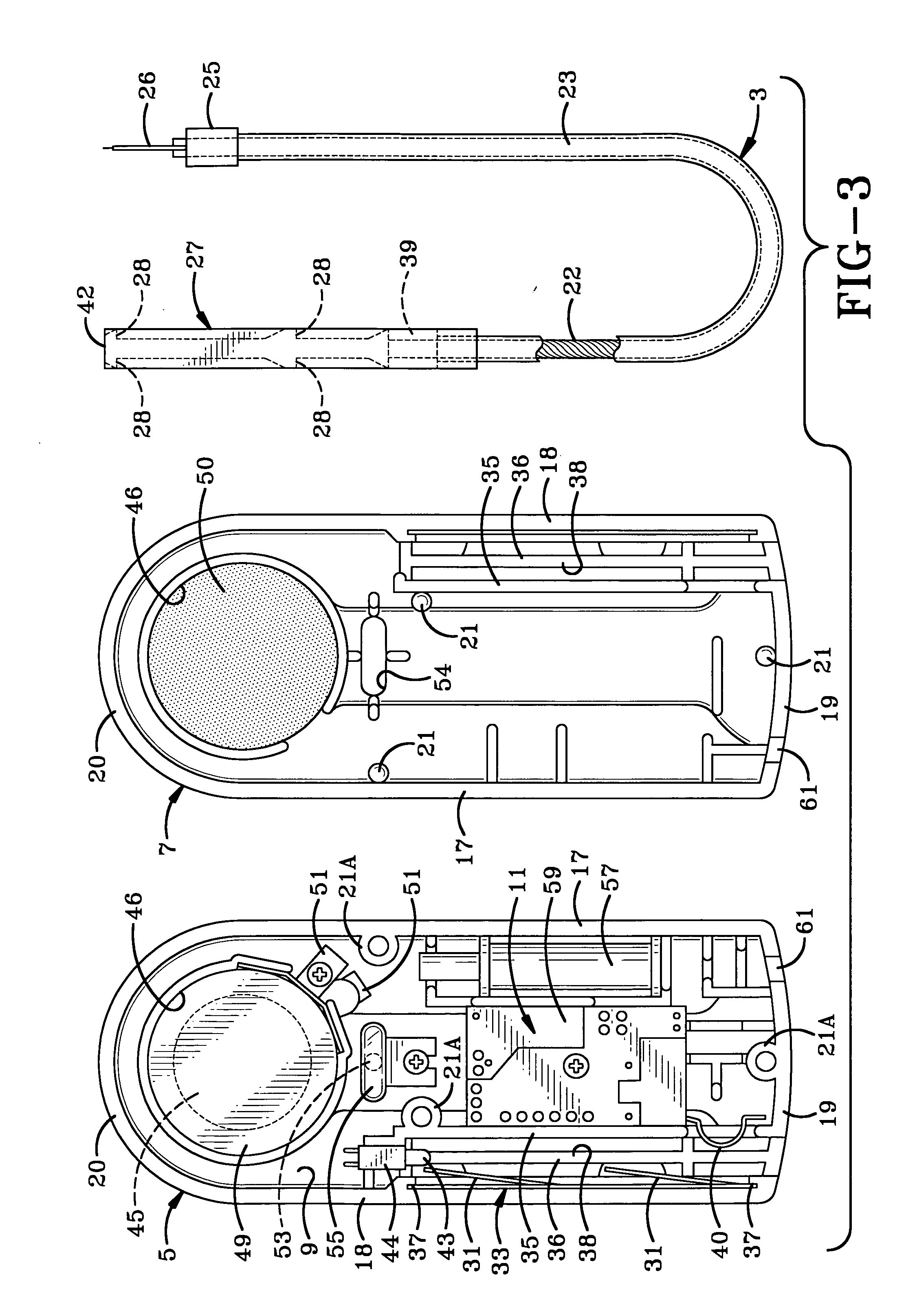
[0029] the cable alarm security device of the present invention is indicated generally at 1, and is shown in FIGS. 1-6. Device 1 includes a main housing 2 and a locking cable 3. Housing 1, as shown in FIG. 3, includes two generally half body components indicated generally at 5 and 7, which are secured together such as with an adhesive or sonic weld, along a seam 8 which extends in a continuous manner completely about the housing as shown in FIGS. 1 and 2. Housing components 5 and 7 preferably are molded of a rigid plastic material and form a hollow internal chamber 9 in which is mounted an alarm system indicated generally at 11 (FIG. 3), the details of which are discussed further below, and a lock mechanism indicated generally at 13.

[0030] Housing 2 has a relatively elongated relatively flat configuration as shown In FIGS. 1 and 2, wherein the thickness (FIG. 2) is considerably less than its length (FIG. 1). This provides a relatively compact yet pleasingly attractive device. Housin...


PUM


Abstract

A security device for attachment to an article to deter theft of the article has a housing containing an alarm system including an audible alarm and an LED. A cable has one end attached to the housing and a second end attached to a plug which is selectively inserted into and locked to the housing. The cable includes a conductor electrically connected to the alarm system when in the locked position. The audible alarm is activated if the integrity of the cable is compromised. An EAS tag located in the housing will actuate an alarm at a security gate and can actuate the audible alarm of the security device when the device is in proximity to a security gate. The LED is positioned in the housing to be visible from both sides of the housing. A magnetically attractable lock mechanism releasably secures the cable plug in the locked position.

Description

CROSS REFERENCE TO RELATED APPLICATION [0001] This application claims the benefit of U.S. Provisional Patent Application Ser. No. 60 / 644,193, filed Jan. 14, 2005.BACKGROUND OF THE INVENTION [0002] 1. Technical Field [0003] The invention relates to theft deterrent devices, and particularly to an EAS tag carrying device that is secured to an item to deter theft thereof. More particularly, the invention relates to such a security device that is connected to an item of merchandise by a cable which is locked thereon by a magnetically attractable locking mechanism, and which has an internal alarm which is actuated if the integrity of the cable is compromised and upon the secured item approaching a security gate sensor. [0004] 2. Background Information [0005] Various retail establishments use theft deterrent systems and devices to discourage shoplifting. Many of these theft deterrent devices use electronic article surveillance (EAS) tags attached to the item of merchandise. The tags are co...

Claims


Application Information

Patent Timeline
Patent Type & Authority Applications(United States)
IPC IPC(8): G08B13/14
CPCE05B45/005E05B67/003E05B73/0017E05B73/0052G08B13/1463G08B13/2434G08B13/248
Inventor MARSILIO, RONALD M.FAWCETT, CHRISTOPHER J.
Owner CHECKPOINT SYST INC
Learn More