Eureka AIR delivers breakthrough ideas for toughest innovation challenges, trusted by R&D personnel around the world.

Method and system for predictive stratigraphy images

Active Publication Date: 2006-07-20
BAKER HUGHES INC
View PDF15 Cites 51 Cited by
  • Summary
  • Abstract
  • Description
  • Claims
  • Application Information

AI Technical Summary

Benefits of technology

[0013] Examples of the more important features of the invention thus have been summarized rather broadly in order that the detailed description thereof that follows may be better understood, and in order tha

Problems solved by technology

This type of measurement does not provide for determining an image of subsurface formation reflectors before the drill bit has reached the reflectors.
Surface seismic surveys generally include this type of information, but resolution and depth location of these data may be poor because surface seismic surveys are time based (rather than depth based) and the low frequencies generally available are not conducive for high resolution.
Offset data is often inadequate however due to horizontal variations in stratigraphy between wells.

Method used


Image

  • Method and system for predictive stratigraphy images
  • Method and system for predictive stratigraphy images
  • Method and system for predictive stratigraphy images

Examples


Embodiment Construction

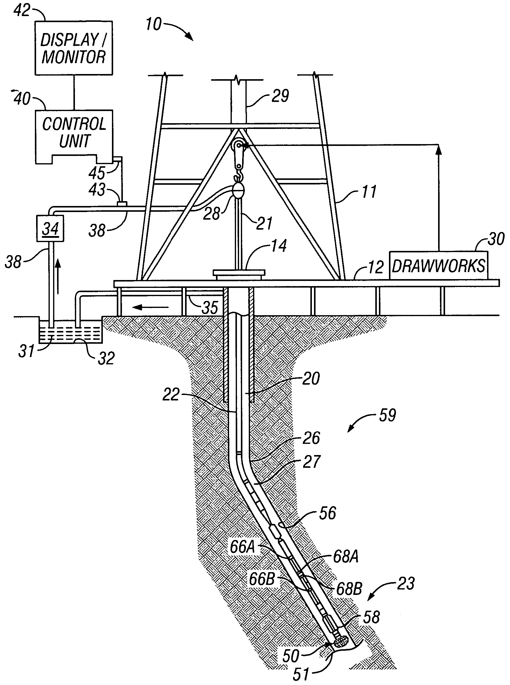
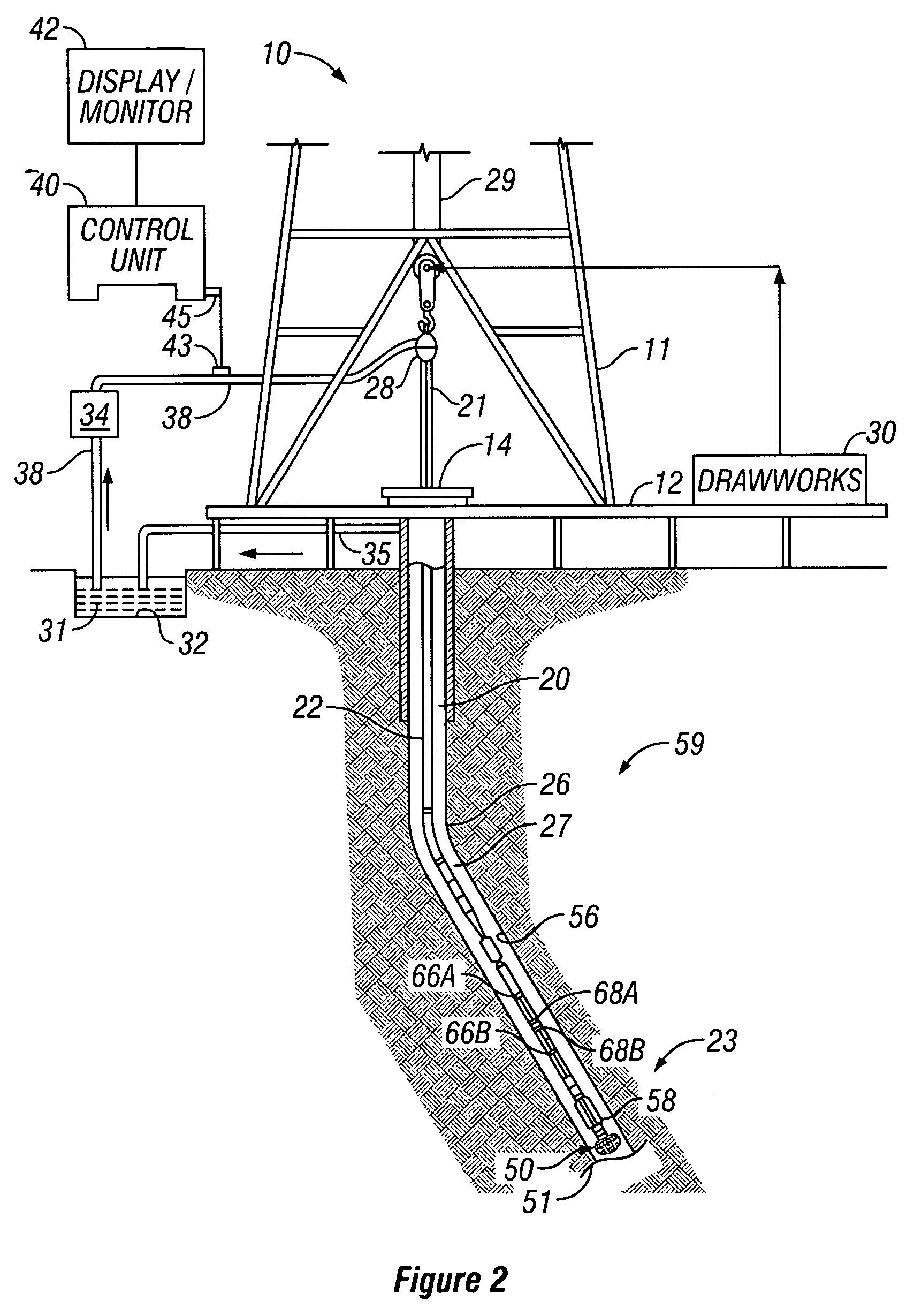
[0030] The present invention is a method and system for a displaying lithology along a well bore path and is useful for direct comparison with geological and or structural cross-section displays. The lithology display provided by the present invention (herein termed the Predictive Stratigraphy Image or PSI) may be displayed along with geological cross-sections and conventional well bore images as well as with property cross-section displays of the subsurface environment. The present invention overcomes the deficiencies of prior methods, for example the difficulty in choosing bed boundary positions directly from image logs and conventional logging measurements. Other advantages of the invention will be readily apparent to persons skilled in the art based on the following detailed description. While the invention is herein described in connection with various embodiments, it will be understood that the invention is not limited thereto. To the extent that the following detailed descrip...


PUM


Abstract

Methods and systems are provided for displaying and forecasting the lithology and wellbore conditions to be encountered while conducting drill string operations are conducted in a wellbore. A method and system is described for predicting and modeling lithology while operating a drill string in a wellbore, comprising: developing a 3-D lithological model of a subsurface area; projecting a well path through said subsurface area; determining an open cylinder lithology display of said projected well path; and recording said determined open cylinder display. The open cylinder lithology display (the Predictive Stratigraphy Image) may be displayed with geological or structural cross-sections to compare the well path and the predicted well path, with the actual subsurface environment. Data acquired during drilling operations can be used in real time to update the model or the Predictive Stratigraphy Image, and the results compared with Predictive Image Logs and other wellbore images and data.

Description

CROSS REFERENCES TO RELATED APPLICATIONS [0001] This application claims priority from U.S. Provisional Patent Application No. 60 / 627,569 filed on Nov. 12, 2004.BACKGROUND OF THE INVENTION [0002] 1. Field of the Invention [0003] This invention relates to the field of subsurface reservoir development, to a method of geosteering and for a system predicting the subsurface environment ahead of a drill bit. The methods and systems are related generally to drilling and measurement systems and more particularly to a system of drilling boreholes having a measurement-while-drilling or logging-while-drilling (MWD or LWD) tool wherein the tool measurements are used to predict and guide the drilling operation. [0004] 2. Description of the Related Art [0005] In the oil and gas industry, those skilled in the art have long recognized the importance of obtaining various borehole measurements during the course of a drilling operation. Typically, these measurements include such data as the weight impo...

Claims


Application Information

Patent Timeline
IPC IPC(8): G06G7/48
CPCE21B7/046E21B47/022E21B47/026G01V11/00G01V2210/6163G01V2210/6167
Inventor KELFOUN, FLORENT
Owner BAKER HUGHES INC
Why Eureka
Eureka Blog
Learn More