Air-bag device

a technology for airbags and vent holes, which is applied in the direction of pedestrian/occupant safety arrangements, vehicular safety arrangements, vehicle components, etc., can solve the problems of complex and expensive methods for closing vent holes, slow response speed, and varied closing speeds, etc., and achieves low cost and reliability protection for occupants. , the effect of closing in a short tim

Inactive Publication Date: 2006-07-13
ASHIMORI INDS
View PDF5 Cites 22 Cited by
  • Summary
  • Abstract
  • Description
  • Claims
  • Application Information

AI Technical Summary

Benefits of technology

[0017] According to the invention as set forth in the above items (1), (2), (3) and (4), the vent hole can be closed by merely releasing retention of the other end of the cloth-like piece, so that a closing mechanism of the vent hole is simple and low in cost and the closing of the vent hole can be carried out with reliability. Further, since gas can be discharged through the vent hole by way of a pocket functioning as a gas reservoir, impact to be applied to the occupant at the time of expansion of the airbag can be eased with reliability.
[0018] According to the invention as set forth in the above item (5), since the vent hole can be closed in a short time by releasing retention of the cloth-like piece by forc...

Problems solved by technology

However, since the device in the patent reference 1 has a structure to close the vent hole by operating the actuator made of the plate-like piezoelectric element and the like, there is a drawback in that a mechanism to close the vent hole is complex and expensive, and also a response speed is slow.
Further, since the patent reference 2 has a system to close the ven...

Method used


Image

  • Air-bag device
  • Air-bag device
  • Air-bag device

Examples


first embodiment

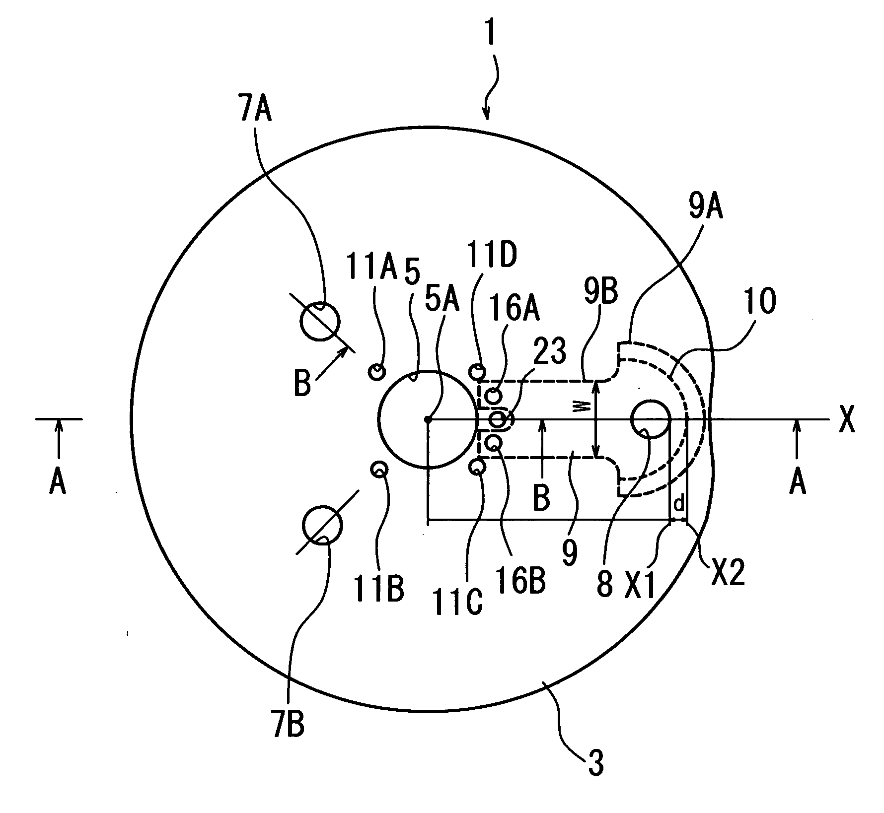
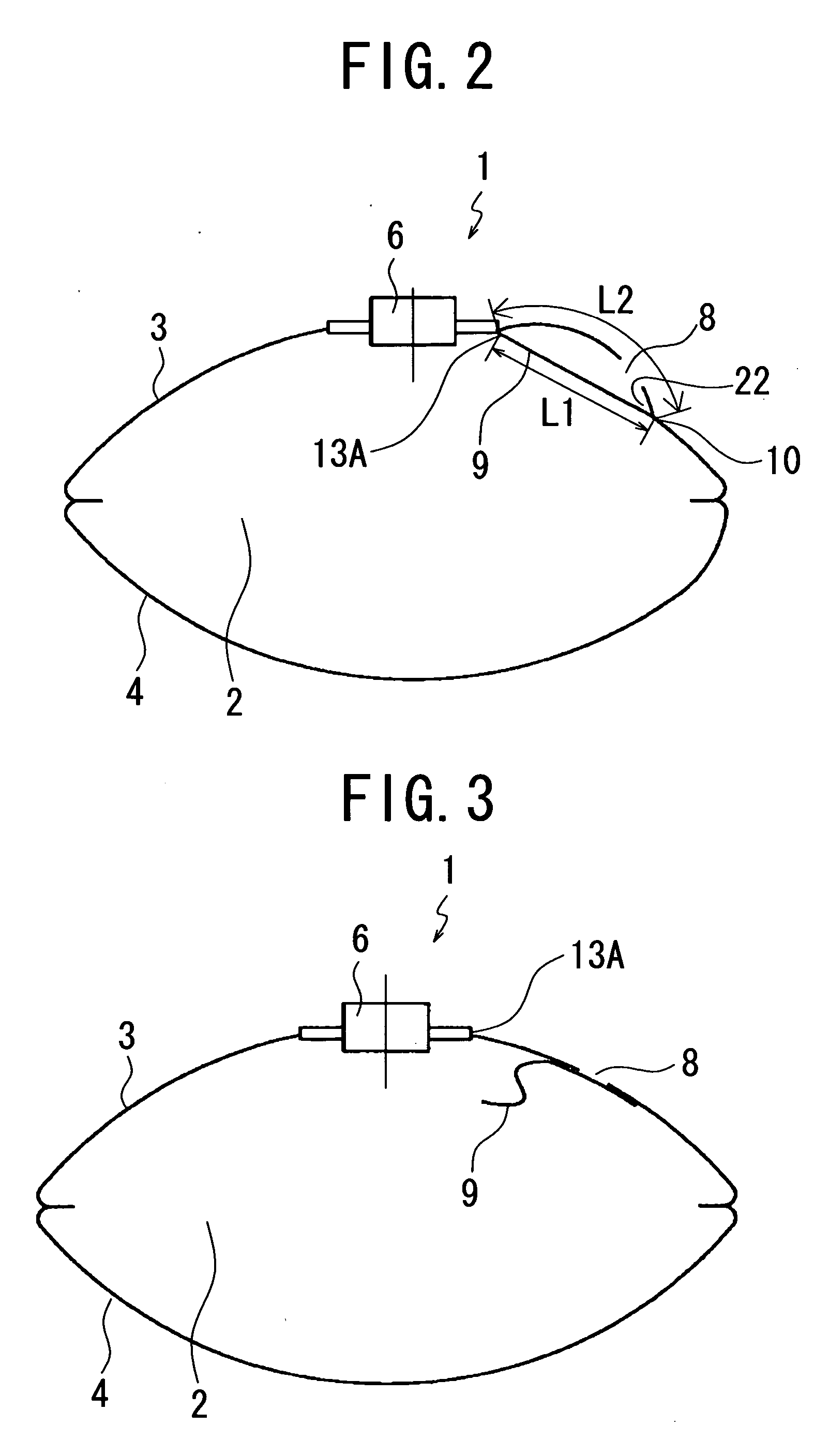
[0036] An airbag device according to the invention is described hereinafter with reference to the accompanying drawings. FIG. 1 is a plan view showing a state where an airbag device 1 is expanded, which shows a state where an inflator is removed. FIG. 2 is a sectional view taken along line A-A in FIG. 1 showing a state where the inflator is fitted. As shown in FIG. 1 and FIG. 2, the airbag device 1 is formed of the airbag 2 comprised of an attachment side base cloth 3 having a circular shape and an opposed side base cloth 4 having also the circular shape wherein peripheries of the attachment side base cloth 3 and opposed side base cloth 4 are sewn together and reversed to form the airbag 2 having a bag-like shape. The attachment side base cloth 3 is located at a side to be fitted to a vehicle together with the inflator 6 while the opposed side base cloth 4 is located at a side to face the occupant and receives the occupant when the airbag 2 is expanded. The inflator 6 is fitted to a...

second embodiment

[0046] As shown in FIG. 8, FIG. 10 and FIG. 11, a first tether belt 28 is stretched between an inside end face 6A of the inflator 6 and a central portion 4A of the opposed side base cloth 4. That is, an upper end of the first tether belt 28 is put in the inside end face 6A of the inflator 6 by a presser plate 26, and the presser plate 26 is fixed to the inside end face 6A by two bolts 25, 25, thereby fixing the first tether belt 28 to the inside end face 6A. The lower end of the first tether belt 28 is sewn and fixed to the central portion 4A of the opposed side base cloth 4. Further, a lower end of a second tether belt 27 is sewn and fixed to the opposed side base cloth 4 at a substantially intermediate position 28A of the first tether belt 28 in the longitudinal direction thereof. Further, an upper end 27A of the second tether belt 27 is detachably fitted to the presser plate 13 together with the cloth-like piece 9, described later. In a state where the upper end 27A of the second...


PUM


Abstract

In an airbag (2), a length extending from a sewn portion (10) to a right periphery of a presser plate (13) is set such that a length (L1) is shorter than a length (L2) wherein the length (L2) is at an attachment side base cloth (3) side and the length (L1) is at a cloth-like piece (9) side. When the airbag (2) is expanded in emergency situations, the attachment side base cloth (3) is expanded while it moves away outwardly from the cloth-like piece (9), thereby opening a vent hole (8), so that the airbag (2) is eased in abrupt expansion directing toward an occupant. When the airbag (2) becomes a sufficient size to protect the occupant, it bends instantaneously a retaining plate (17) to release the parallel portion (9B) of the cloth-like piece (9) from the presser plate (13), so that the cloth-like piece (9) is brought into intimate contact with the attachment side base cloth (3) to close the vent hole (8), thereby protecting the occupant with reliability.

Description

FIELD OF THE INVENTION [0001] The invention relates to an airbag device whose airbag is deployable at the time of collision of a vehicle to protect an occupant, more particularly to an airbag device capable of precisely controlling an expansion speed of an airbag in the midway of the expansion. BACKGROUND OF THE INVENTION [0002] An airbag device fitted to a driver seat and a passenger seat of a vehicle is to protect an occupant by rapidly expanding an airbag by means of a gas pressure let out from an inflator at the time of collision of the vehicle. In the airbag device described above, it is necessary to ease influence of impact given to the occupant when the airbag is expanded, thereby receiving the occupant softly by the airbag. To that end, it is preferable to avoid a situation where the airbag is abruptly expanded to protrude toward the occupant when the inflator operates. Particularly, since the occupant comes into contact with the airbag in a short time in the case where the ...

Claims


Application Information

Patent Timeline
IPC IPC(8): B60R21/20B60R21/239B60R21/16B60R21/233B60R21/2338B60R21/276
CPCB60R21/2338B60R21/2342B60R21/239B60R2021/23382
Inventor YAMAJI, NAOKIAZUMA, HIDETAKA
Owner ASHIMORI INDS
Why Eureka
Try Eureka