Nozzle for a random selection machine
a random selection machine and nozzle technology, applied in the field of nozzles, can solve the problems of inability to evenly stir balls in the barrel, inability to evenly gather balls, etc., and achieve the effect of increasing the speed of the air
- Summary
- Abstract
- Description
- Claims
- Application Information
AI Technical Summary
Benefits of technology
Problems solved by technology
Method used
Image
Examples
first embodiment
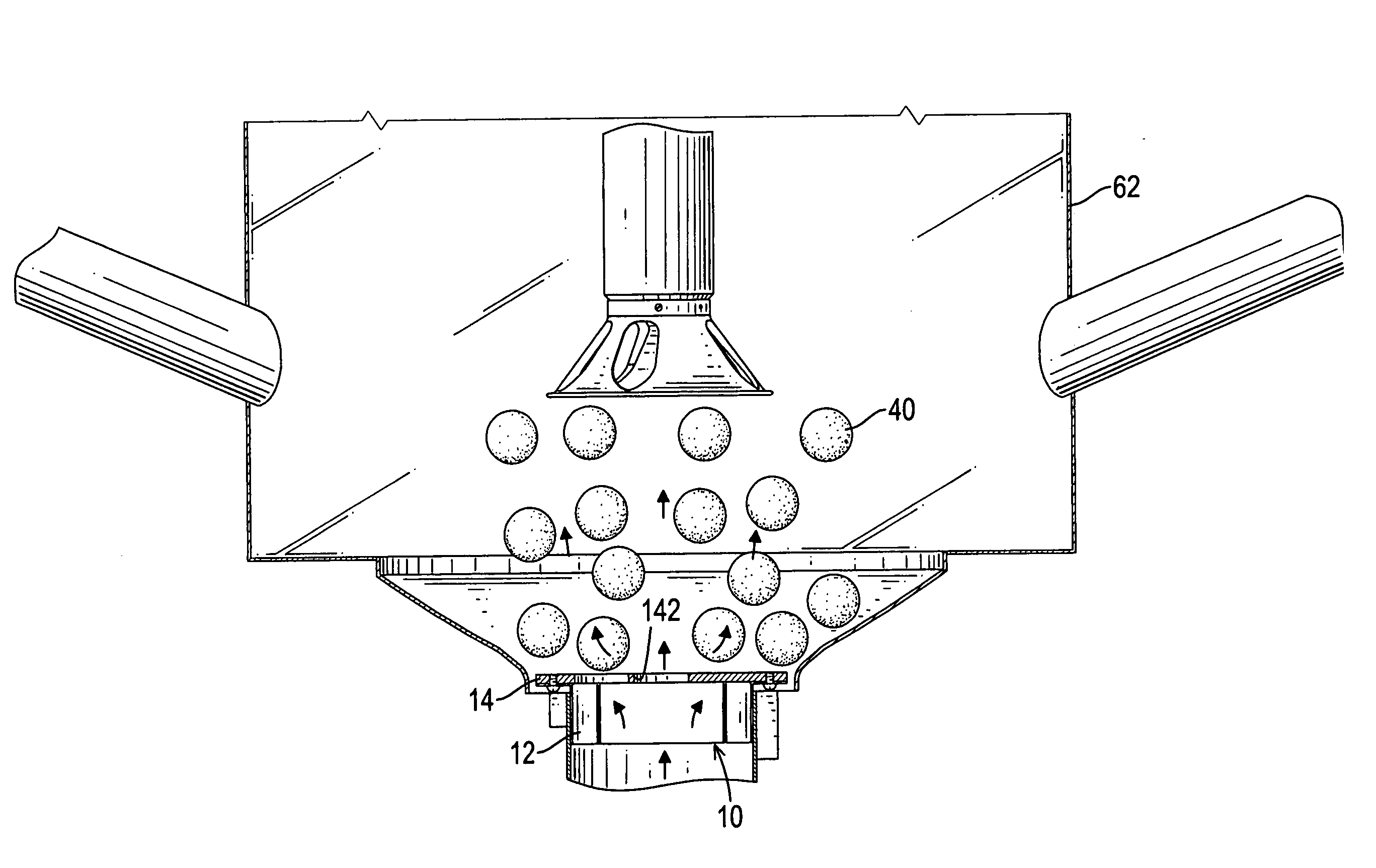
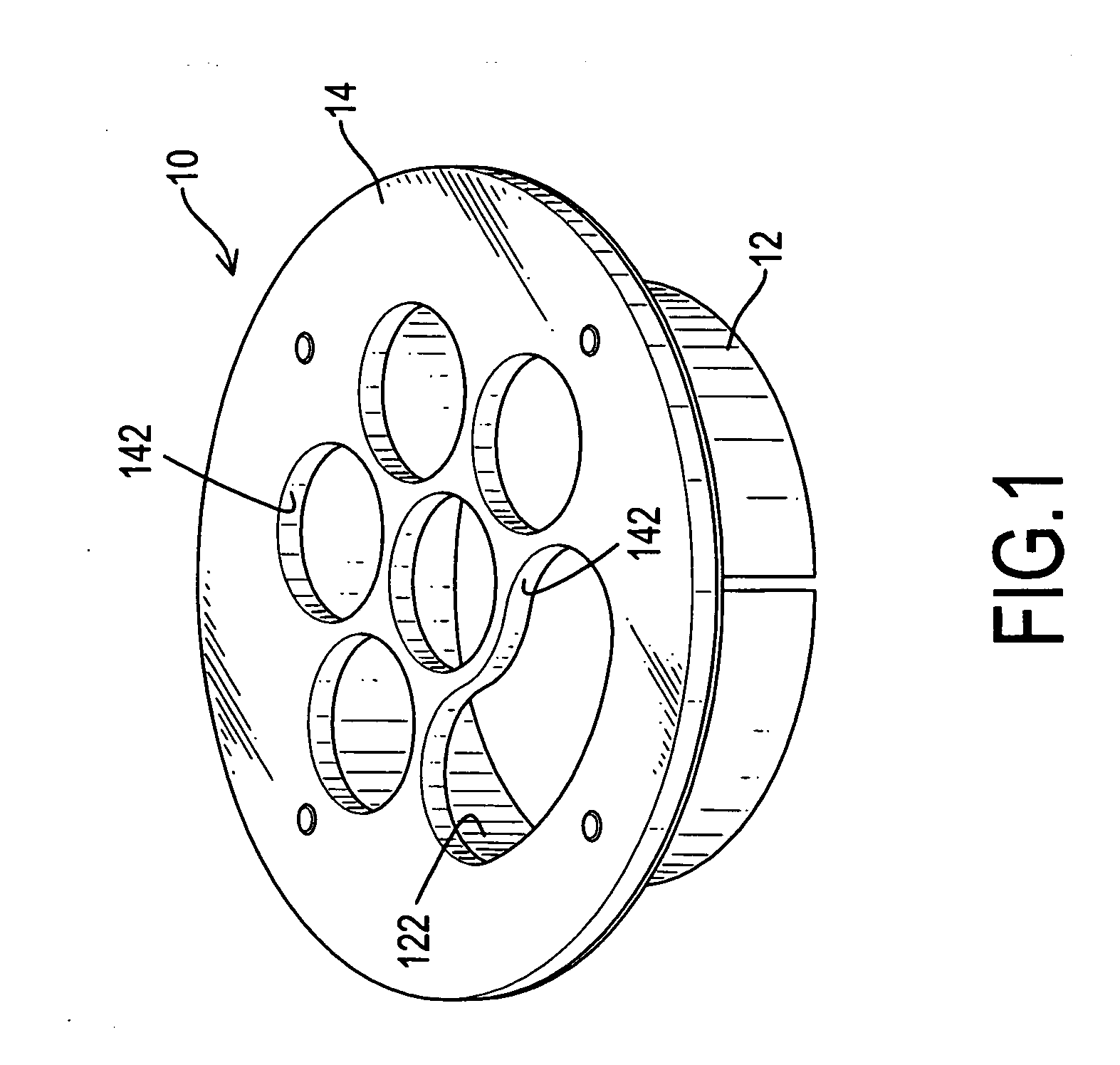
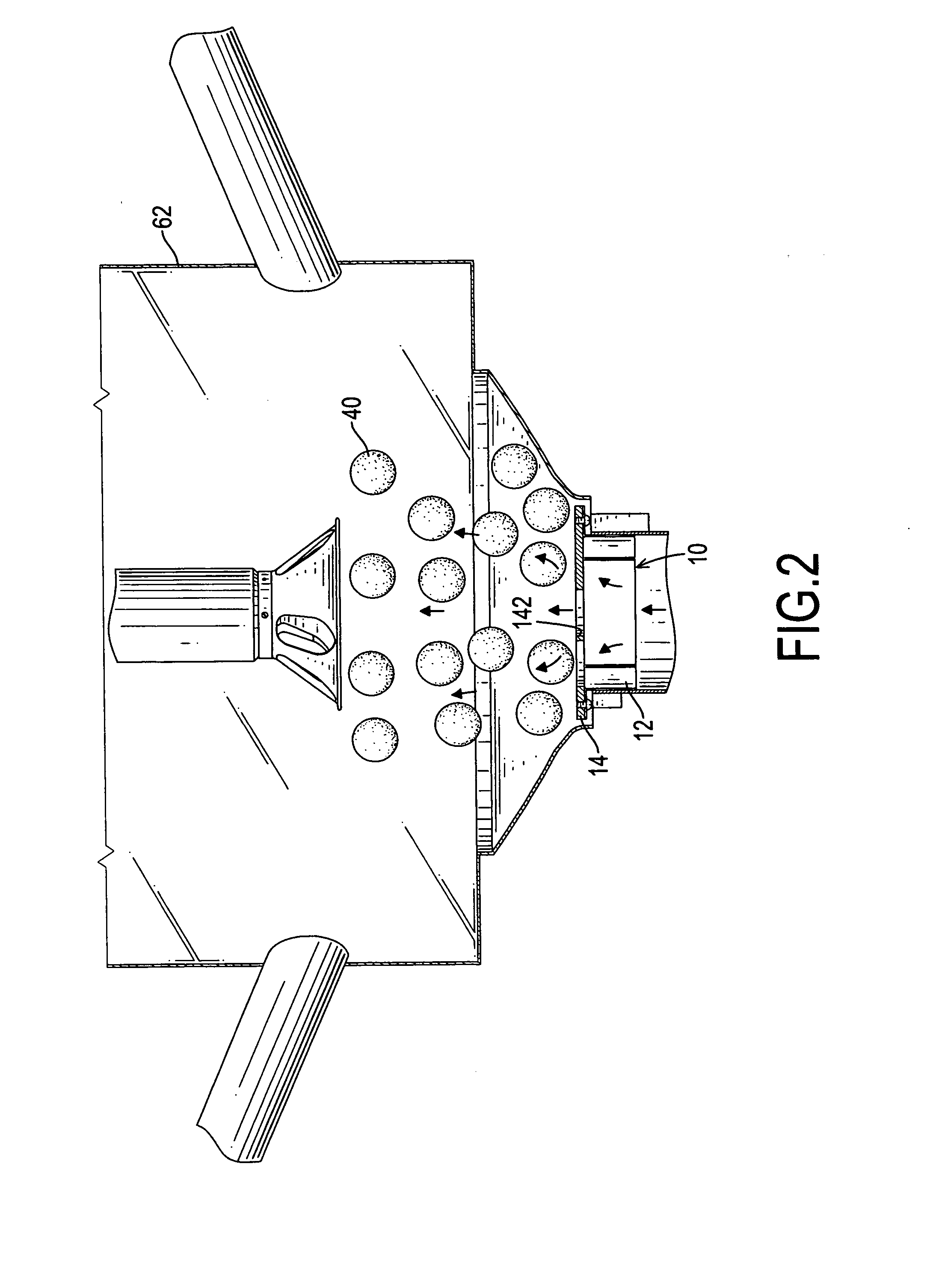
[0019] With reference to FIGS. 1 and 2, a body (10) of a nozzle in accordance with the present invention comprises a connecting tube (12) and a top flange (14). The connecting tube (12) has a top and a central passage (122) defined through the connecting tube (12). The top flange (14) is attached to the top of the tube (12) to close the central passage (122) and has multiple bores (142) defined through the flange (14) and communicating with the central passage (122) in the connecting tube (12). With the bores (142) in the top flange (14), multiple laminar flow passages are defined.
[0020] In such an arrangement, when air is blown into a barrel (62) through the nozzle, the airflow exhausting out from the blower will be compressed by the bores (142) in the nozzle. The airflow will be divided into multiple jetting laminar flows due to the bores (142) in the top flange (14) even when turbulent flow has generated. Consequently, turbulent flow will not easily occur at a location near the n...
second embodiment
[0021] With reference to FIGS. 3 and 4, a body (20) of a nozzle in accordance with the present invention comprises a connecting tube (22), a top flange (24) and a guiding plate (26). The connecting tube (22) has a top and a central passage (222) defined through the tube (22). The top flange (24) is attached to the top of the tube (22) to close the central passage (222) and has a center and multiple bores (242) defined through the flange (24) and communicating with the central passage (222) in the connecting tube (22). With the bores (242) in the top flange (24), multiple laminar flow passages are defined. The guiding plate (26) extends upward from the center of the top flange (24). In a preferred embodiment, a protrusion (25) is formed on the center of the top flange (24), and the guiding plate (26) is formed on and extends upward from the protrusion (25). The protrusion (25) further has multiple through holes (252) defined through the protrusion (25) and communicating with the cent...
third embodiment
[0023] With reference to FIGS. 5 and 6, a body (30) of a nozzle in accordance with the present invention comprises a connecting tube (32), a top flange (34), a guiding plate (36) and guiding collar (38). The connecting tube (32) has a top and a central passage (322) defined through the tube (32). The top flange (34) is attached to the top of the tube (32) to close the central passage (322) and has a center and multiple bores (342) defined through the flange (34) and communicating with the central passage (322) in the connecting tube (32). With the bores (342) in the top flange (34), multiple laminar flow passages are defined. The guiding plate (36) extends upward from the center of the top flange (34). In a preferred embodiment, a protrusion (35) is formed on the center of the top flange (34), and the guiding plate (36) is formed on and extends upward from the protrusion (35). The protrusion (35) further has a top and multiple through holes (352) defined through the protrusion (35) ...
PUM
 Abstract
Description
Claims
Application Information
 - R&D
- Intellectual Property
- Life Sciences
- Materials
- Tech Scout
- Unparalleled Data Quality
- Higher Quality Content
- 60% Fewer Hallucinations
Browse by: Latest US Patents, China's latest patents, Technical Efficacy Thesaurus, Application Domain, Technology Topic, Popular Technical Reports.
© 2025 PatSnap. All rights reserved.Legal|Privacy policy|Modern Slavery Act Transparency Statement|Sitemap|About US| Contact US: help@patsnap.com


