
System and method for fault identification in an electronic system based on context-based alarm analysis

a technology of context-based alarm analysis and fault identification, applied in the field of fault identification in electronic systems, can solve the problems of accurate fault identification, ambiguity and redundancy, difficult diagnostic task of electronic systems, etc., and achieve the effect of reducing ambiguity and complexity and efficient identifying faults

Inactive Publication Date: 2006-07-06
TECH MAHINDRA INDIA
View PDF13 Cites 46 Cited by
  • Summary
  • Abstract
  • Description
  • Claims
  • Application Information

AI Technical Summary

Benefits of technology

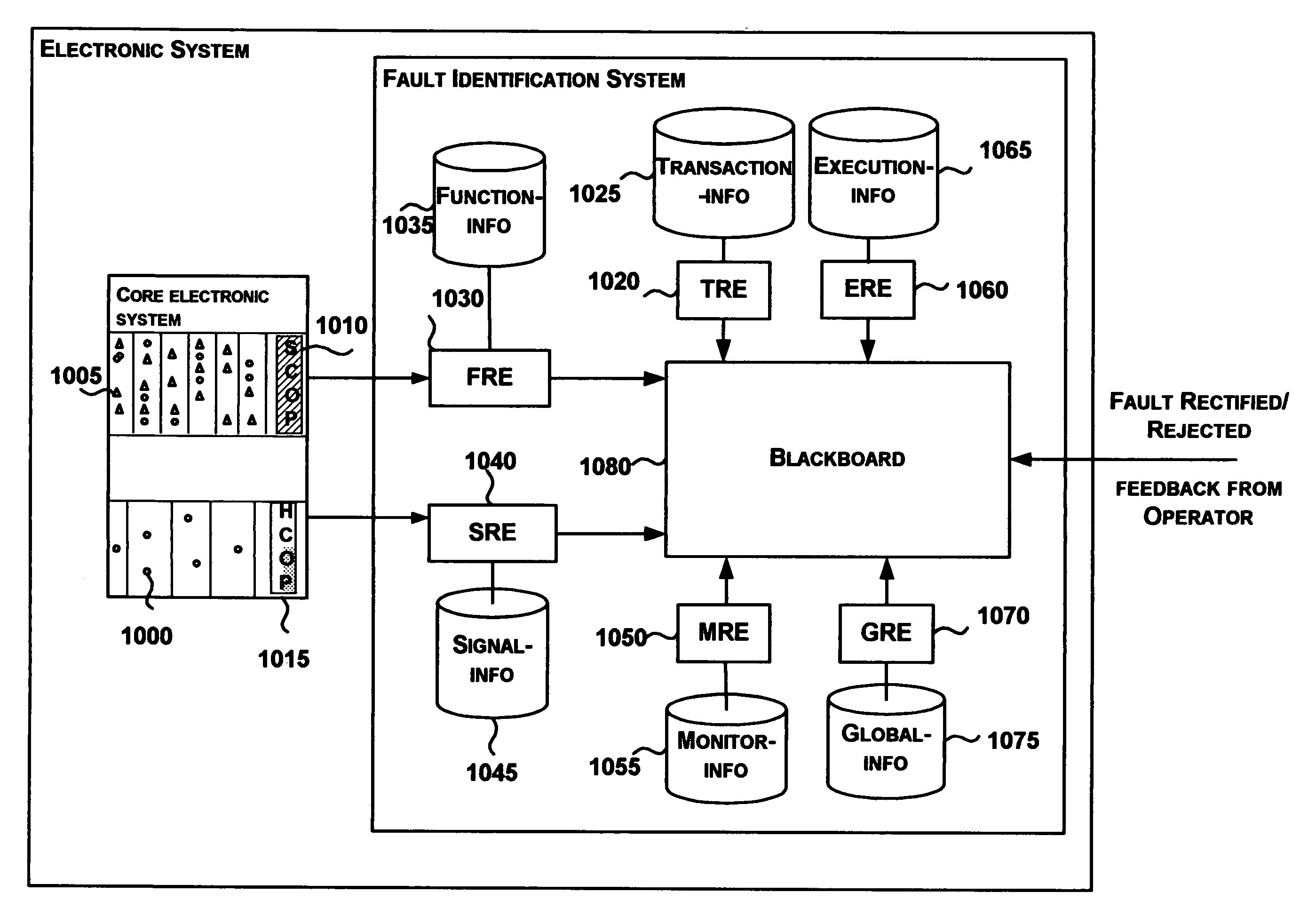
[0033] The present invention provides a method and apparatus for efficiently identifying the faults occurring in an electronic system based on the analysis of observed alarm information. More specifically, the present invention provides methods for reducing the ambiguity and complexity arising due to the enormity of the alarms generated by the system.
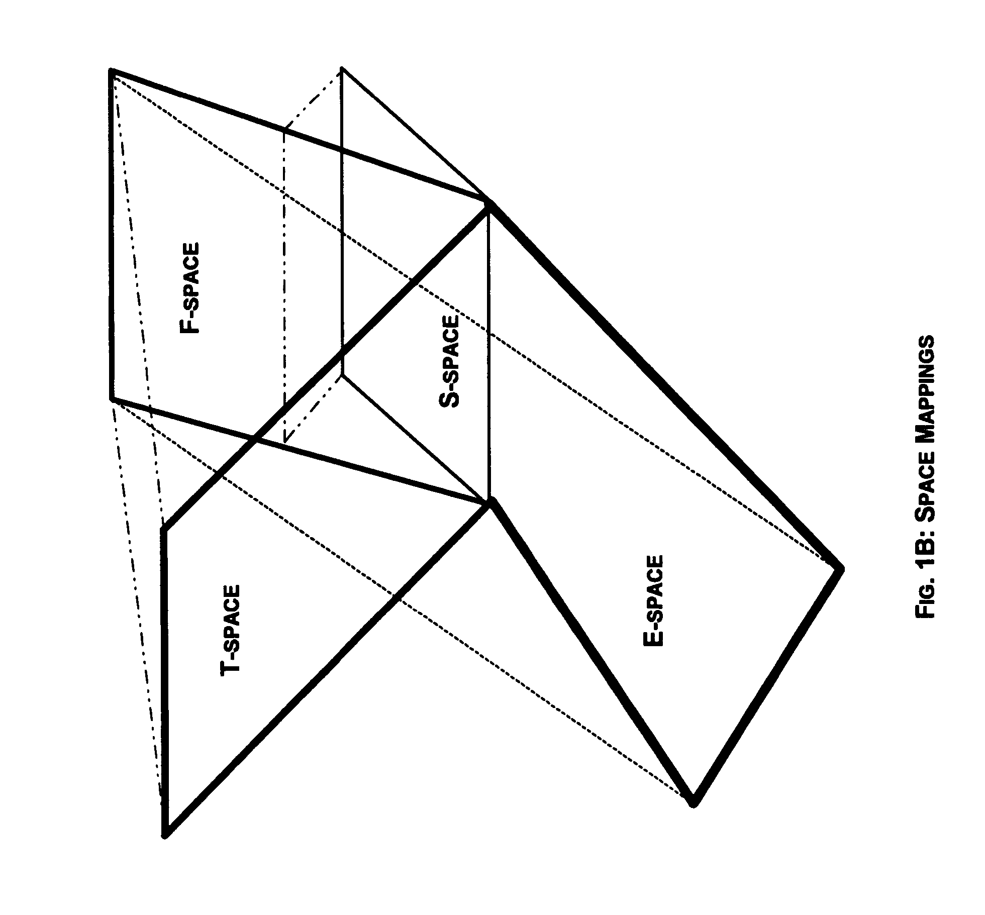
[0034] One aspect of the invention is to provide for the definition of additional contextual information associated with the alarms by observing the electronic system along the four dimensions namely, Transaction-space, Function-space, Execution-space and Signal-space. Each of these spaces provide additional contextual information for the alarms generated and thus enhancing the semantic content of the alarms.
[0038] Yet another aspect of the invention is a definition of a process for the design of the system based on the “Design for Diagnosis” approach. DFD approach is an enhanced hardware-software co-design methodology to improve the diagnosibility of the system. This methodology provides a process to collect the knowledge and database information during the system design and to identify contextual information and design of means for collecting the contextual information from CES at run-time.
[0039] Present invention is advantageous in reducing the complexity of alarm processing arising out of enormity of alarms by logically grouping them based on transactions.

Problems solved by technology

Diagnosing an electronic system is a challenging task despite the availability of enormous alarm information.
The ambiguity and redundancy associated with alarm information presents a challenge for fast and accurate fault identification.
Probability networks are ineffective if they cannot produce hypotheses with a precise confidence level.
The known systems do not address the issue of exploiting a multidimensional context associated with a plurality of alarms in identifying and localizing faults in an electronic system.

Method used


Image

  • System and method for fault identification in an electronic system based on context-based alarm analysis
  • System and method for fault identification in an electronic system based on context-based alarm analysis
  • System and method for fault identification in an electronic system based on context-based alarm analysis

Examples


example 1

[0131] Consider the following four sample annotations:

Annotation 1=[a1, a2, a5*] where a5* indicates that zero or more alarms can get generated

Annotation 2=[a1, a6+, a8] where a6+indicates that 1 or more alarms can get generated

Annotation 3=[a9, a1, a10, a11]

Annotation 4=[a6, a7]

On occurrence of first alarm a1, annotations 1, 2, and 3 contain the alarm a1 and hence these are selected for defining the derived segments.

[0132] DS1=[a1] based on comparison with Annotation 1

DS2=[a2] based on comparison with Annotation 2

[0133] DS3=[a9, a1] based on comparison with Annotation 3 and although alarm a1 has occurred, a9 is missing. TRE analyses the information related to the associated AMV to validate the support for the missing alarm, and based on the support for the occurrence of the missing alarm, the derived segment is updated.

[0134] In case when the alarm received is not the first one in the transaction (2320), TRE checks the generated alarm with respect to each of the DSs (2...


PUM


Abstract

A fault identification system analyzes alarm information and the associated contextual information to identify the occurred faults. The contextual information is based on usecases, transactions, and functions associated with the electronic system under consideration. Multiple detectors that form part of knowledge repositories are used in the process of fault identification.

Description

FIELD OF INVENTION [0001] The present invention relates to the field of fault identification in an electronic system and more particularly, to identify the occurrence of a fault in a complex electronic system based on alarm processing. Still more particularly, the invention relates to systems and methods for efficient alarm analysis and fault identification based on context based analysis. BACKGROUND OF THE INVENTION [0002] Fault isolation in electronic devices such as network elements and communication switches is a challenging task due to enormity of alarm data, ambiguous alarm information (false or missing alarms, redundant alarms, out of sequence alarms etc.) and insufficient alarm-based information for some faults. Hence, there is a need for a mechanism for fast and efficient processing of a large number of alarms. [0003] Existing solutions for fault isolation are mainly of the following categories based on the approach employed for fault diagnosis and isolation: [0004] Rule Ba...

Claims


Application Information

Patent Timeline
Patent Type & Authority Applications(United States)
IPC IPC(8): G06F11/00H04L1/22
CPCH04L1/22
Inventor S., VEENASRIDHAR, G.SRIDHAR, V.RAO, K. KALYANA
Owner TECH MAHINDRA INDIA
Learn More