
Methods and systems for spring design and analysis

a spring and design technology, applied in the field of spring design and analysis, can solve the problems of not revealing the design process of such a spring, not addressing the dynamic aspects of spring design, and the springs encountering severe stress and strain

Inactive Publication Date: 2006-07-06
CATERPILLAR INC
View PDF7 Cites 12 Cited by
  • Summary
  • Abstract
  • Description
  • Claims
  • Application Information

AI Technical Summary

Problems solved by technology

Often under extreme operating conditions, the springs encounter severe stress and strains.
Orloff, however, does not disclose how such a spring may be designed absent the traditional trial and error technique.
Existing tools do not account for dynamic aspects of spring design.
However, this approach is not reliable for springs that will encounter dynamic forces in operation.
Considering only static stress may result in springs that encounter spring load loss and fatigue failures during operation.

Method used


Image

  • Methods and systems for spring design and analysis
  • Methods and systems for spring design and analysis
  • Methods and systems for spring design and analysis

Examples


Embodiment Construction

[0022] Reference will now be made in detail to the drawings. Wherever possible, the same reference numbers will be used throughout the drawings to refer to the same or like parts.

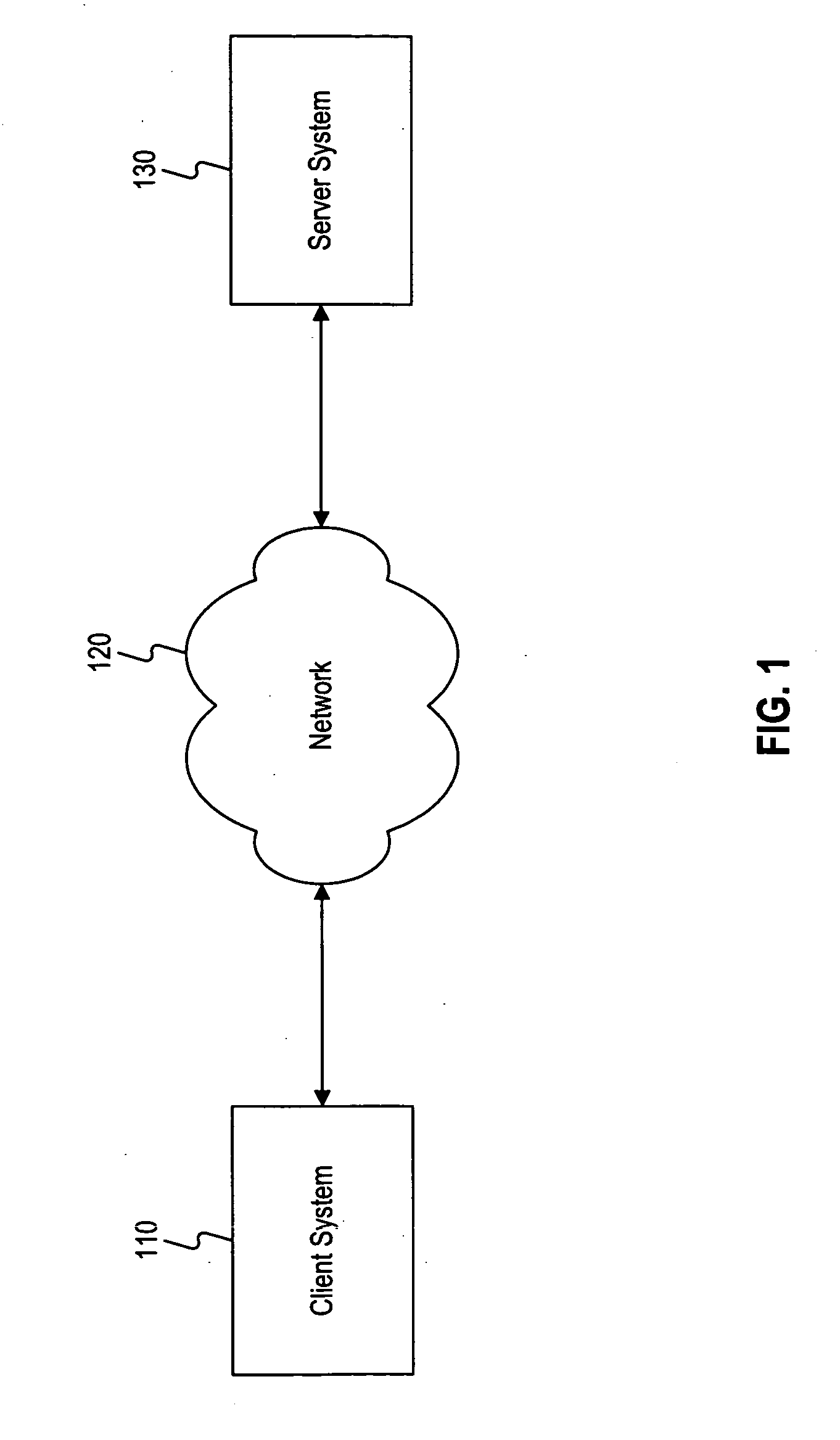
[0023]FIG. 1 illustrates an exemplary system environment in which features and principals consistent with the present disclosure may be implemented. As shown, the exemplary system environment may include a client system 110, a network 120 and a server system 130. Although FIG. 1 shows only one client and only one server, one skilled in the art would realize that any number of these elements may be implemented within the computing environment shown in FIG. 1 without departing from the scope of the present disclosure.

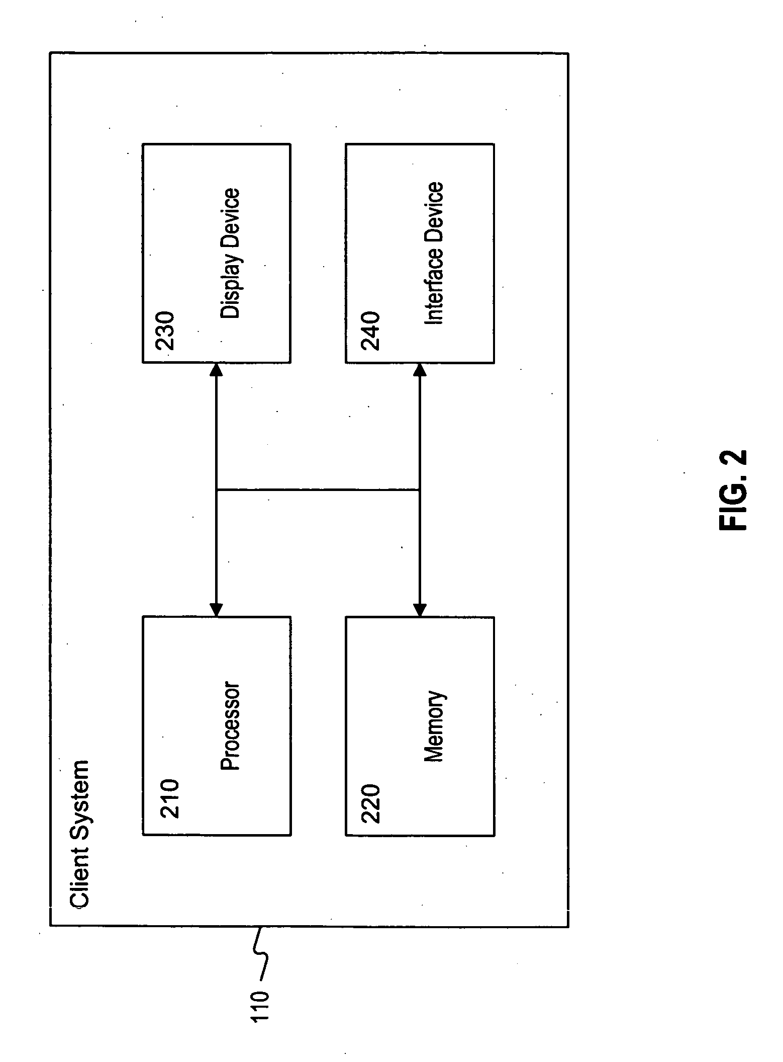
[0024] Client system 110 may be a desk top computer, work station, lap top, personal digital assistant, or any other similar computer system known in the art. For example, client system 110 may include a processor, associated memory, and numerous other elements and functionalities available in ...


PUM


Abstract

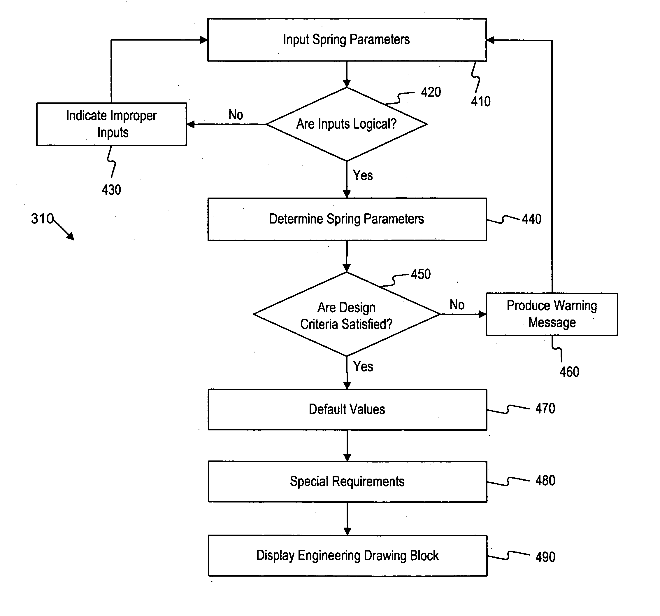
A spring design method is disclosed. The method begins with inputting a first set of design parameters for a spring. The design parameters include a parameter that provides an estimate of non-linearity in the spring. The spring design method determines a spring design based on the first set of design parameters. A spring design and analysis method is disclosed. The method begins with creating a spring design. The spring design includes a parameter that provides an estimate of non-linearity in the spring design. The spring design and analysis method creates a spring animation file that enables stress levels in a spring design to be identified at the coil level. The spring design method next identifies the coil in the spring design having the lowest dynamic fatigue factor and determines whether the lowest dynamic fatigue factor is acceptable.

Description

TECHNICAL FIELD [0001] This disclosure relates generally to spring design and analysis. More particularly, the disclosure relates to systems and methods for designing and analyzing non-linear and linear springs under dynamic loading conditions. BACKGROUND [0002] Helical compression springs and other springs are important components in numerous mechanical devices. Often under extreme operating conditions, the springs encounter severe stress and strains. For example, helical compressions springs are used in fuel systems to control loads and injection timing. These fuel systems deliver accurate volumes of fuel for precise timing and provide multiple injections for low emissions with complete combustion and maximum fuel economy. Fuel system springs experience high dynamics due to rapid acceleration and deceleration during and after injection events. Fuel systems springs have been pushing the current spring design methodologies to the technical limit in order to improve fatigue life and ...

Claims


Application Information

Patent Timeline
IPC IPC(8): G06G7/48G06F17/50
CPCB60G2206/99G06F17/5018G06F30/23F16F1/00G06F30/17
Inventor EL-SAYED, SAMI IBRAHIMSANDHU, AVTAR SINGHCOLDREN, DANA RAYSEFFAL, RABAH
Owner CATERPILLAR INC
Learn More