
Reduced-friction catheter introducer and method of manufacturing and using the same

a technology of introducer and reducer, which is applied in the field of medical devices, can solve the problems of insufficient rigidity, insufficient rigidity, and insufficient rigidity of rope, and achieve the effect of reducing or eliminating frictional for

Active Publication Date: 2006-07-06
CR BARD INC
View PDF99 Cites 68 Cited by
  • Summary
  • Abstract
  • Description
  • Claims
  • Application Information

AI Technical Summary

Benefits of technology

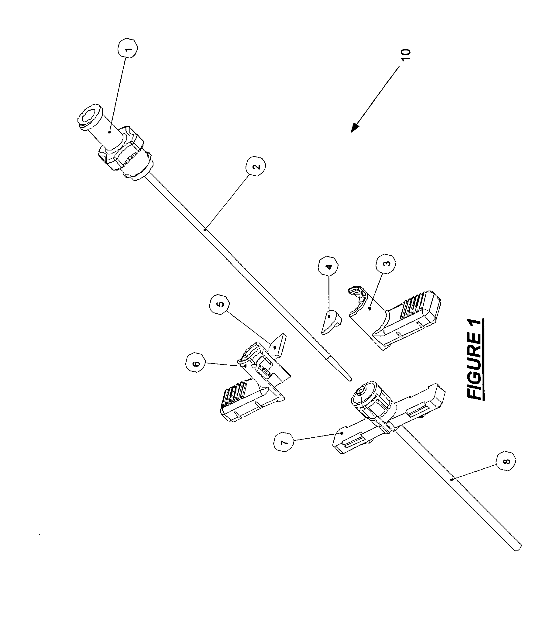
[0012] The invention relates to tear-away and non-tear-away sheath introducers for catheters, methods for making such introducers, and methods for using such introducers. The sheath introducers contain movable valves that are encapsulated in a movable housing unlike conventional valves that are stationary. The movable housing allows the valve to move along the axis of the introducer. As the movable valve and housing travel along the axis, a portion of the hub protrudes past the valve and is exposed. The protruding portion of the hub contains a friction-free pathway for the catheter into the sheath introducer. The introducers can therefore be used with any catheter, regardless of the size or material, because of the reduced or eliminated frictional force between the catheter and introducer.

Problems solved by technology

But inserting smaller catheters into smaller introducers is more difficult.
This open configuration exists because smaller catheters, due to their smaller diameter and material, are not rigid enough to overcome the frictional forces needed to push the catheter through the valve.
In other words, it is like trying to “push” a rope through a hole: the rope does not remain rigid enough for a user to push it through the hole.
The open configuration between the vascular system and the environment, however, allows two serious clinical problems.
First, air embolism into the vascular system which can result in patient injury and / or death.
And second, release of potentially infectious bodily fluids (including blood) into the environment, resulting in exposure to the health care provider.

Method used


Image

  • Reduced-friction catheter introducer and method of manufacturing and using the same
  • Reduced-friction catheter introducer and method of manufacturing and using the same
  • Reduced-friction catheter introducer and method of manufacturing and using the same

Examples


Embodiment Construction

[0028] The following description provides specific details in order to provide a thorough understanding of the invention. The skilled artisan, however, would understand that the invention could be practiced without employing these specific details. Indeed, the invention can be practiced by modifying the illustrated method and resulting device and can be used in conjunction with apparatus and techniques conventionally used in the industry. For example, the invention is described as a micro-introducer for small catheters (3F-10F in size), but could easily be adapted for any size of catheter or device regardless of the size or intended use. Further, while the invention is described for use with catheters for vascular access, it could be used with any similar device that is used to grant a physician (or other user) access to a part of the body, whether human or animal.

[0029] The invention includes a tear-away or non-tear-away sheath introducer that contains a movable valve and housing ...


PUM


Abstract

Tear-away and non-tear-away sheath introducers for catheters, methods for making such introducers, and methods for using such introducers are described. The sheath introducers contain movable valves that are encapsulated in a movable housing unlike conventional valves that are stationary. The movable housing allows the valve to move along the axis of the introducer. As the movable valve and housing travel along the axis, a portion of the hub protrudes past the valve and is exposed. The protruding portion of the hub contains a friction-free pathway for the catheter into the sheath introducer. The introducers can therefore be used with any catheter, regardless of the size or material, because of the reduced or eliminated frictional force between the catheter and introducer.

Description

REFERENCE TO RELATED APPLICATION [0001] This application claims priority of U.S. Provisional Application Ser. No. 60 / 631,397, filed on Nov. 29, 2004, the disclosure of which is incorporated herein by reference.FIELD OF THE INVENTION [0002] The invention relates to medical devices and methods for manufacturing such medical devices. In particular, the invention relates to introducers for catheters, methods for making such introducers, and methods for using such introducers. More particularly, the invention relates to self-sealing sheath introducers (both tear-away and non-tear-away), methods for manufacturing such introducers, and methods of using such introducers in medical procedures. BACKGROUND OF THE INVENTION [0003] Tear-away sheath introducers (“sheath introducers” or “introducers”) and their use as medical devices are well known in the art. See, for example U.S. Pat. Nos. 6,814,718, 6,808,520, 6,808,509, 6,796,991, 6,740,101, 6,712,791, 6,712,789, 6,695,810, 6,641,564, 6,632,23...

Claims


Application Information

Patent Timeline
Patent Type & Authority Applications(United States)
IPC IPC(8): A61F11/00
CPCA61M25/0668
Inventor KING, ERICWORTLEY, RONALD
Owner CR BARD INC
Learn More