Power injection catheters and method of injecting

a technology of injection catheter and power injection, which is applied in the direction of catheter, intravenous device, other medical devices, etc., can solve the problems of thrombosis, failure of catheter wall, and inability to provide a clear indication to the operator, so as to prevent overpressurization, high flow rate applications, and high pressure

Active Publication Date: 2006-07-06
CR BARD INC
View PDF91 Cites 44 Cited by
  • Summary
  • Abstract
  • Description
  • Claims
  • Application Information

AI Technical Summary

Benefits of technology

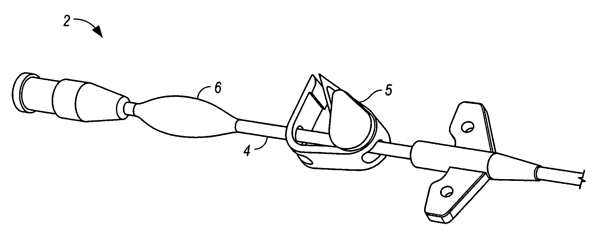
[0007] Described herein are catheters for infusing fluids into a patient's body. Some variations of the catheter are configured for high flow rate applications. These catheters, which are configured for infusing large amounts of fluids in a short period of time, are termed “power injection catheters.” The catheters may be configured to support high pressure inside its lumen to sustain high pressure generated by rapid infusion. In addition, a pressure relief mechanism may be provided on the catheter to prevent overpressurization.
[0010] Also, a further aspect of the instant disclosure relates to a method of injecting a fluid into a patient's body. Specifically, a catheter may be inserted into a circulatory system of a patient. In further detail, the catheter may include at least one lumen and at least one extension tube comprising a proximal valve, the at least one extension tube capable of fluid communication with the at least one lumen of the catheter. Also, the proximal valve may be structured to inhibit fluid flow for pressures developed within the at least one lumen of the catheter below a selected aspiration pressure. A pressure exceeding the selected aspiration pressure may be developed within the at least one lumen of the catheter by injecting a fluid into the at least one lumen of the catheter. Additionally, fluid flow through the at least one extension tube comprising the proximal valve may be prevented.

Problems solved by technology

It has been observed that during injection of a contrast media at high flow rates into a small-sized lumen, the sudden increase in pressure inside the lumen may lead to failure of the catheter wall.
In addition, catheters that are implanted in a patient's body for a period of time may have thrombus build-up within the lumen of the catheter.
These thromboses may occlude the catheter and cause overpressurization when the catheter is flushed.
Furthermore, in a pressure protection device that is based on a compliant balloon, the balloon will typically enlarge gradually in response to pressure, and therefore does not provide a clear indication to the operator when a critical pressure threshold has been breached.
Thus, in applications where high pressure injections are required, the operators may have difficulty determining whether overpressurization has occurred by observing the condition of a partially inflated balloon alone.
In addition, many of these designs may fail at high pressure, such as 300 psi or above.
These designs tend to have a low pressure threshold, and, as a result, the overall fluid throughput is also relatively low.
Sudden pressure spikes due to initial introduction of fluid pressure, unanticipated obstruction within the catheter, or operator error, may temporarily force the pressure inside the catheter to exceed the breaking threshold (i.e., burst value) of the catheter.

Method used


Image

  • Power injection catheters and method of injecting
  • Power injection catheters and method of injecting
  • Power injection catheters and method of injecting

Examples


Embodiment Construction

[0046] The following detailed description should be read with reference to the drawings, in which like elements in different drawings may be identically numbered. The drawings, which are not necessarily to scale, depict selected preferred embodiments and are not intended to limit the scope of the present invention. The detailed description illustrates by way of example, not by way of limitation, the principles of the present invention. This description will clearly enable one skilled in the art to make and use the invention, and describes several embodiments, adaptations, alternatives and uses of the invention, including what is presently believed to be the best mode of carrying out the invention.

[0047] Before describing aspects of the present invention, it is to be understood that, unless otherwise indicated, this invention need not be limited to applications in humans. As one of ordinary skill in the art would appreciate, variations of the invention may be applied to other mammal...


PUM


Abstract

Power injection catheters for high flow rate delivery of fluids are disclosed. In one embodiment, a catheter may include a body defining one lumen and a plurality of extension tubes each comprising a lumen in fluid communication with the one lumen of the catheter body. Further, an extension tube may be configured for performing power injection and an extension tube may include a proximal valve. In another embodiment, a catheter may comprise a plurality of lumens and extension tubes, each of the extension tubes comprising a lumen in fluid communication with one lumen of the catheter body, respectively. At least one extension tube may be configured for performing power injection and at least one extension tube may include a proximal valve. Such catheters may include a pressure relief mechanism for preventing overpressurizing of the catheter. A method of injecting a fluid into a patient's body is disclosed.

Description

CROSS-REFERENCE TO RELATED APPLICATIONS [0001] This application is a continuation-in-part of U.S. patent application Ser. No. 11 / 029,299, filed 4 Jan. 2005, the disclosure of which is incorporated, in its entirety, by this reference.BACKGROUND [0002] It has been observed that during injection of a contrast media at high flow rates into a small-sized lumen, the sudden increase in pressure inside the lumen may lead to failure of the catheter wall. In addition, catheters that are implanted in a patient's body for a period of time may have thrombus build-up within the lumen of the catheter. These thromboses may occlude the catheter and cause overpressurization when the catheter is flushed. To prevent the sudden pressure spikes, a pressure buffering component may be provided to modulate the pressure inside the catheter lumen. Various other medical applications that require high throughput fluid injection through a catheter may also benefit from having a pressure modulating device integra...

Claims


Application Information

Patent Timeline
IPC IPC(8): A61M31/00
CPCA61M5/007A61M5/1408A61M5/16854A61M2205/3355A61M25/0097
Inventor BREITER, CATHERINE C.DIAMOND, JORDAN P.
Owner CR BARD INC
Why Eureka
Try Eureka