
On-axis electron impact ion source

a technology of electron impact and electron source, which is applied in the field of mass spectroscopy systems, can solve the problems of large ionization volume of the source, impede the focusing of ions, and be unsuitable for rapid gc/ms analysis,

Inactive Publication Date: 2006-07-06
AGILENT TECH INC
View PDF9 Cites 6 Cited by
  • Summary
  • Abstract
  • Description
  • Claims
  • Application Information

AI Technical Summary

Problems solved by technology

In gas chromatography mass spectrometer (GC / MS) systems, there is the further difficulty that space charges of carrier gas ions can also impede the focusing of ions near the ion exit axis.
The large surface area of the ionization chamber makes it infeasible to use the source in the analysis of low concentrations of polarized chemical species.
Furthermore, the large ionization volume of the source can be unsuitable in rapid GC / MS analyses because the gas residence time in the ionization chamber is close to or longer than the length of the detected peaks.

Method used


Image

  • On-axis electron impact ion source
  • On-axis electron impact ion source
  • On-axis electron impact ion source

Examples


Embodiment Construction

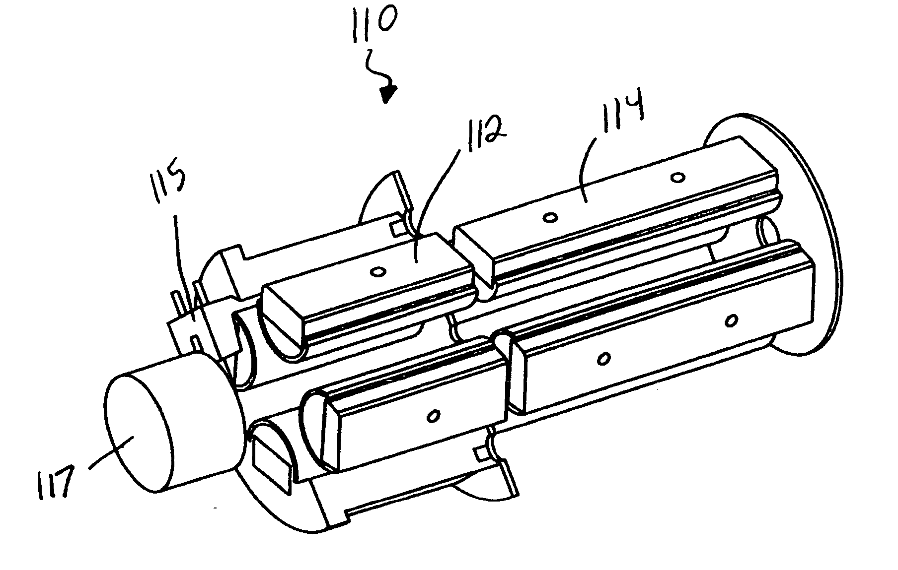
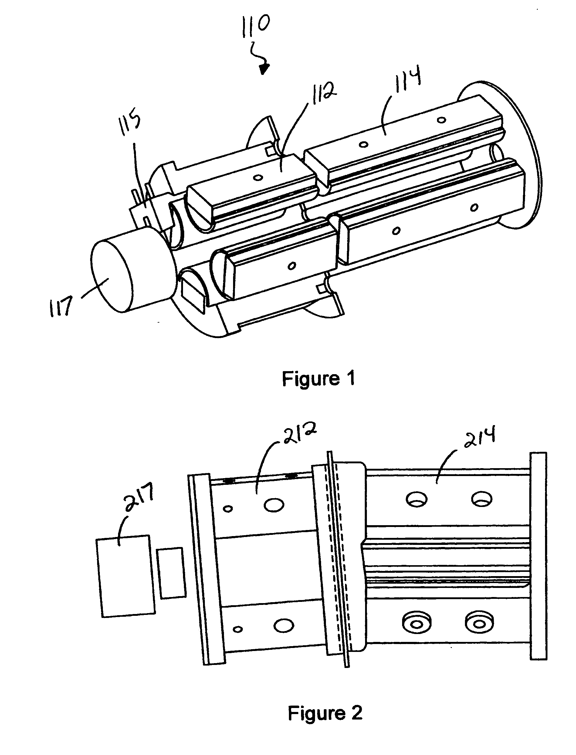
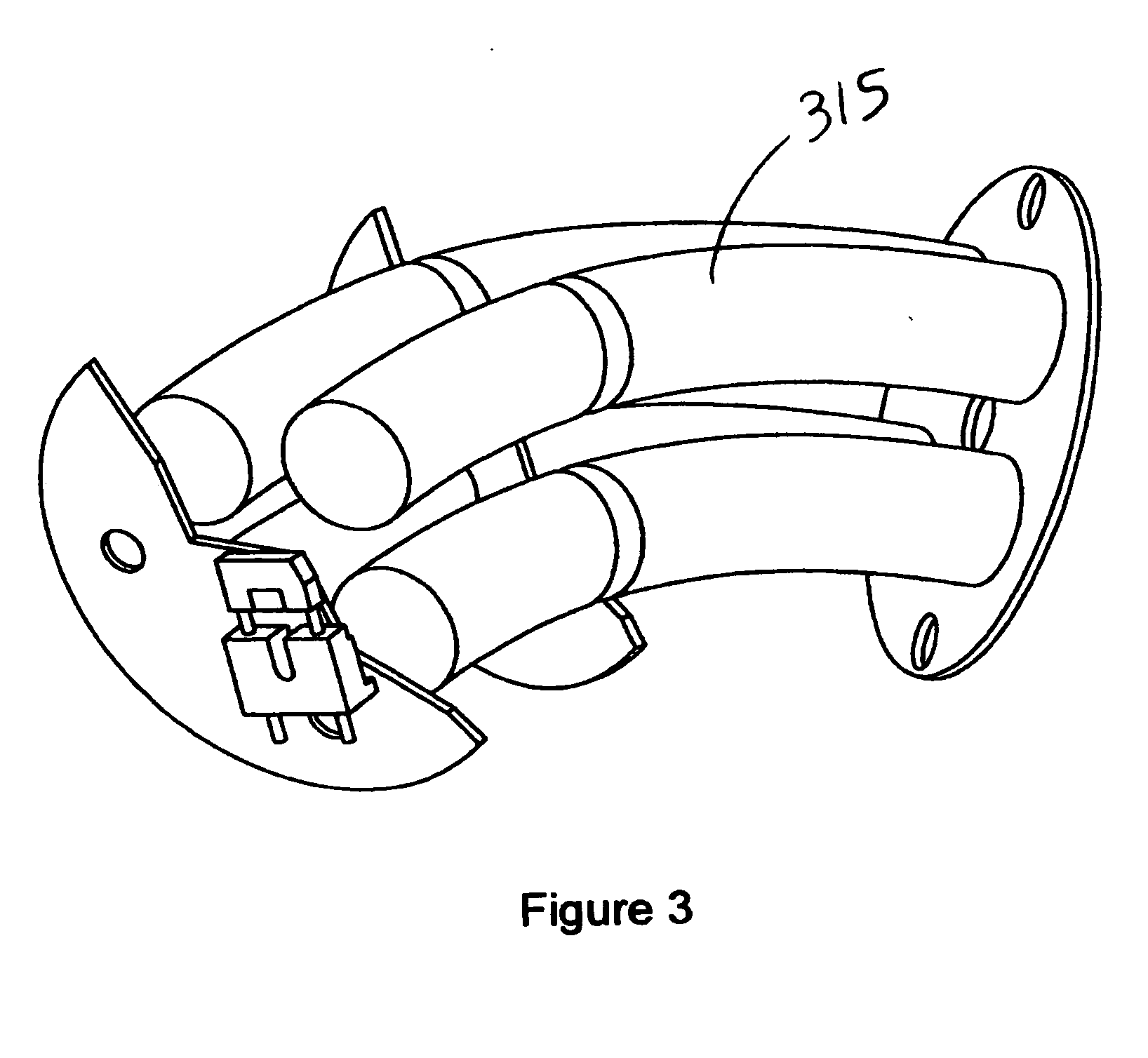
[0012] An example arrangement of components of a GC / MS system is shown in FIG. 4. A charge-neutral liquid or gas sample 101, usually in solution, is vaporized, transported and optionally purified (separated) by gas chromatograph 102. The carrier gas of the gas chromatograph can be helium, hydrogen, nitrogen, neon, argon, for example. The charge-neutral sample gas / carrier gas mixture 103 proceeds into an RF (radio frequency) quadrupole ion source 110. Within the ion source 110, the sample gas is ionized into multiple ions by collision with electrons of a focused electron beam. The temperature in the ion source 110 may range between 20 and 350 degrees Celsius, and the pressure ranges between about 10−1 and about 10−4 torr. Sample ions and / or sample ion fragments emerge from the ion source 110 and move toward ion focus lens 115; as they do so the sample ions tend to converge to the central z-axis of the RF-field within the quadrupole due to collisional damping with carrier and / or dampi...


PUM


Abstract

An electron impact ion source includes an ionization chamber in which a first rf multipole field can be generated and an ion guide positioned downstream from the ionization chamber in which a second rf multipole field can be generated wherein electrons are injected into the ionization chamber along the axis (on-axis) to ionize an analyte sample provided to the ionization chamber.

Description

FIELD OF THE INVENTION [0001] The present invention relates to mass spectroscopy systems, and more particularly, but without limitation, relates to an electron impact (EI) ion source in which electrons are injected into an ionization chamber in the same direction in which ions leave the chamber (on-axis). BACKGROUND INFORMATION [0002] Electron impact ion sources produce analyte ions by exposing analyte molecules to a focused electron beam. In conventional ion sources of this type, electrons are injected into the ionization chamber in a perpendicular direction with respect to the longitudinal axis of the ionization chamber (the ion exit axis, or z-axis). In this configuration, a substantial percentage of the ions are formed off of the ion exit axis, and thus only a reduced portion of ions passes to the mass analyzer for detection. In gas chromatography mass spectrometer (GC / MS) systems, there is the further difficulty that space charges of carrier gas ions can also impede the focusin...

Claims


Application Information

Patent Timeline
Patent Type & Authority Applications(United States)
IPC IPC(8): B01D59/44
CPCH01J49/147H01J49/063
Inventor WANG, MINGDACIRIMELE, EDWARD C.
Owner AGILENT TECH INC
Learn More