
System for improving engine performance and reducing emissions

Inactive Publication Date: 2006-06-22
JURANITCH JAMES C +1
View PDF9 Cites 2 Cited by
  • Summary
  • Abstract
  • Description
  • Claims
  • Application Information

AI Technical Summary

Benefits of technology

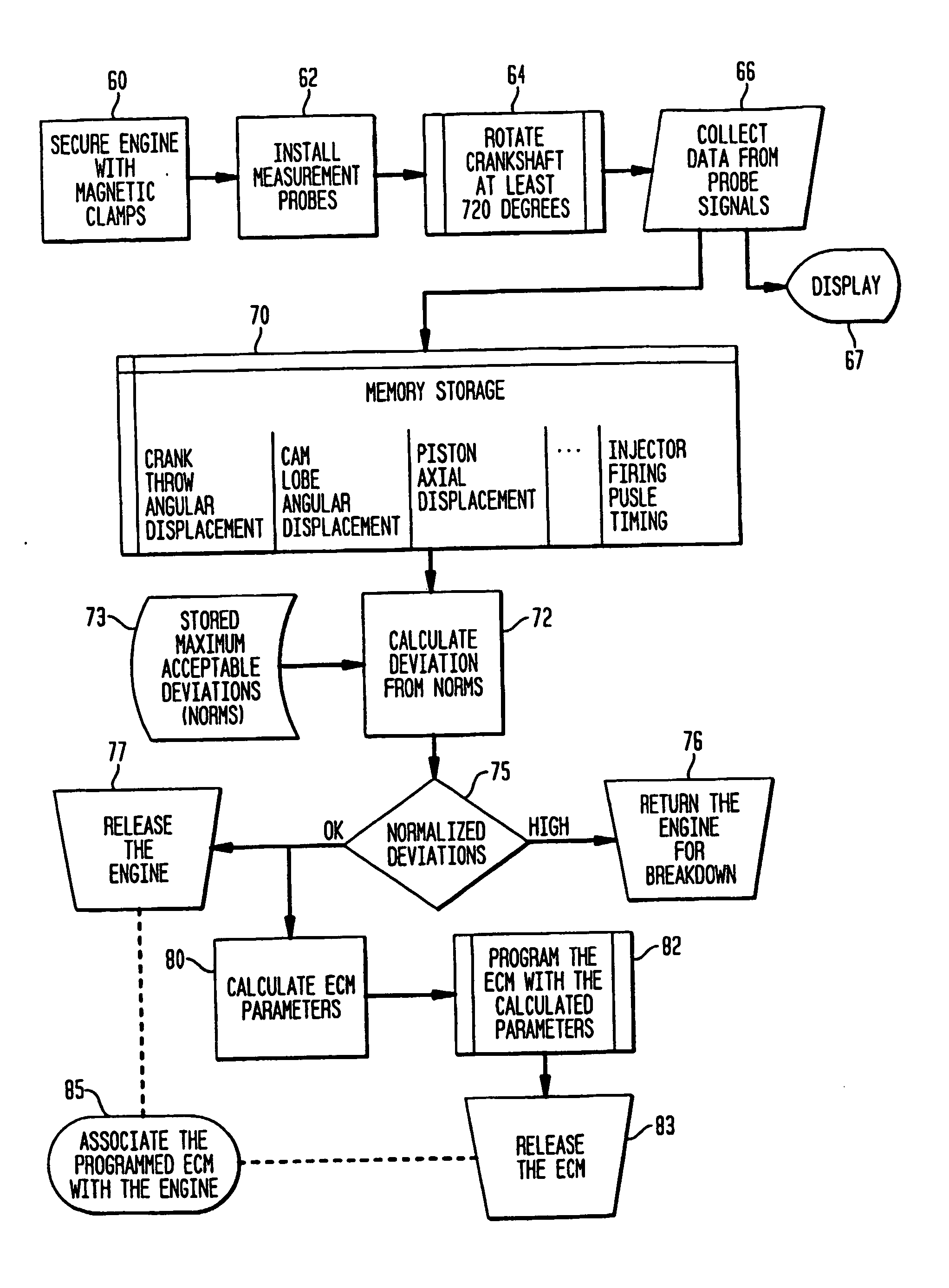
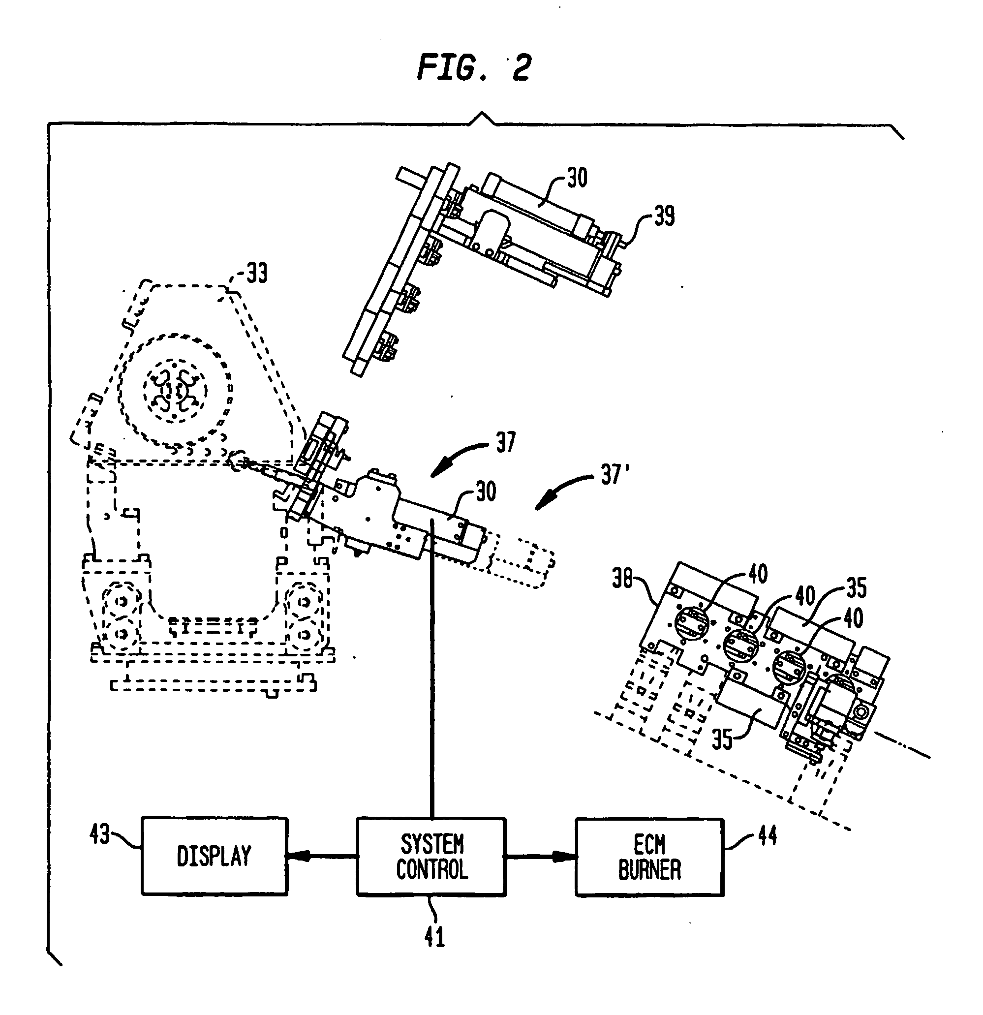
[0009] The foregoing and other objects are achieved by the invention described herein which provides a system for measuring assembly errors introduced during the Diesel engine manufacturing process. In a highly advantageous embodiment of the invention, the assembly errors are determined on a cylinder-by-cylinder basis. Data responsive to such errors is then relayed to an engine control module (ECM) burn station where corrective strategies are implemented electronically to effect reduction in engine emissions and enhance performance. It is to be understood that a simplified embodiment of the inventive arrangement can be implemented in factory service and engine rebuild facilities.
[0048] It is an advantageous characteristic of the present system for measuring and offsetting variables in electronic injection engines that precise acquisition of engine-manufacturing variables is reduced to data that is downloaded to create proper corrective offsets to the engine control module. These offsets can result in increased power, decreased emissions, better mileage, smoother running engines, and less costly components.
[0049] As noted herein, a key point of measurement is individual cylinder top dead center. An accurate measurement of individual top dead center will allow fuel injection timing to be corrected to each cylinder. This will result in an overall increase in engine performance. The main component that can create variables in top dead center is crankshaft “connecting rod pin” angular variation.
[0051] A third point of measurement is valve cam timing relative to top dead center. In most engines, the cam is mechanically driven and timing is generally not adjustable. Therefore, it is important that cam position be accurately checked in a dynamic condition to verify proper valve timing. This will maintain minimum emissions with maximum power. An incorrect cam position can be found early in the engine build process thus allowing easy replacement if required.
[0053] A fourth point of measurement is the injector sensor-timing signal. This sensor normally detects camshaft, or crankshaft positions and triggers the start of injector pulses. An error in this signal can cause improper injector timing resulting in increased emissions, lower performance and decreased engine efficiency.
[0055] A fifth point of measurement is liner height to piston head profile. Variation in this dimension can create excessive crevice volume, resulting in high emissions.

Problems solved by technology

In particular, customers are not willing to suffer reductions in engine performance or reliability, irrespective of the fact that the government has mandated that the emission of pollutants be reduced.
It is a characteristic of such engines that the Diesel cycle is a difficult and complex combustion process on which to reduce emissions.
Nevertheless, the mandated emission standards are extremely strict, and simple, presently available after-treatments, such as catalytic conversion, are largely ineffective in reducing the emissions of Diesel engines.

Method used


Image

  • System for improving engine performance and reducing emissions
  • System for improving engine performance and reducing emissions
  • System for improving engine performance and reducing emissions

Examples


Embodiment Construction

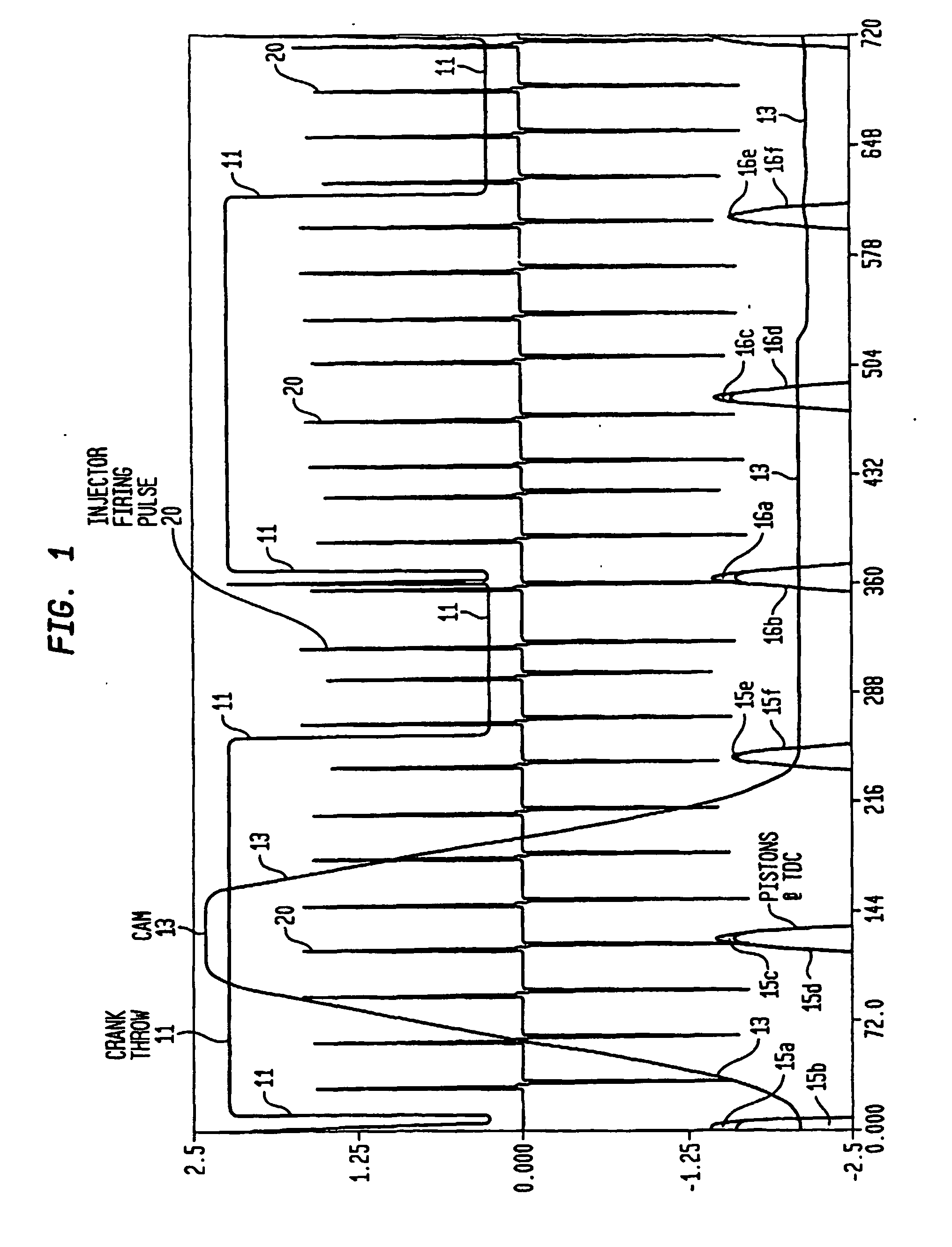
[0070]FIG. 1 is a graphical representation showing various engine characteristics on a common scale of angular displacement. The vertical axis is not specifically dimensioned. The horizontal axis is dimensioned in degrees of rotation, in this example, representing a rotational traversal of the engine (not shown) crankshaft (not shown) of 720°, which corresponds to completion of all engine cycles. The graphical plot labeled “Crank Throw” and designated as crank throw signal 11 illustrates in the vertical at 0° and at 360° the position of the engine crankshaft (not shown) relative to all other measurements. As shown, the graphical plot labeled “Cam” and designated as cam signal 13 is in the form of a lobe related to a fuel pump (not shown) that verifies the actual degree of offset the engine cam (not shown) relative to the crankshaft (not shown). In this specific illustrative embodiment of the invention, cam signal 13 corresponds to the rotation of a single cam lobe, illustratively th...


PUM


Abstract

A method of correcting engine performance in response to assembly deviations includes the steps of measuring the physical characteristics of each cylinder of the engine, and storing the resulting data in the associated ECM. The engine is then operated in accordance with the stored data. The physical characteristics that are measured include, inter alia, a distance of axial displacement of each piston within its associated cylindrical bore; a timing characteristic of the camshaft; a timing of a fuel injection interval; the rate of fuel flow as a function of crankshaft angle of rotation, and a timing characteristic of the crankshaft. Some of the operating parameters that arc controlled during engine operation in response to the data stored in the ECM include, inter alia, the air:fuel ratio and the timing of a fuel injection interval for each piston. These corrections result in increased power, decreased emissions, better mileage, a smoother running engine, and less costly components.

Description

RELATIONSHIP TO OTHER APPLICATION [0001] This application claims the benefit of Provisional Application for U.S. Letters Patent Ser. No. 60 / 393,648, filed Jul. 2, 2002.BACKGROUND OF THE INVENTION [0002] 1. Field of the Invention [0003] This invention relates generally to arrangements and systems for improving the performance of Diesel engines while reducing emissions therefrom, and more particularly, to a system that monitors physical characteristics of a Diesel engine and effects electronic correction therefor. [0004] 2. Description of the Related Art [0005] The Diesel engine manufacturing industry is under increasing pressure to reduce emissions, yet maintain or improve engine performance. The market for such engines is mature and competitive. It is another characteristic of the market that production capability of Diesel engines greatly exceeds demand in the current market. Customers demand high value and do not feel compelled to pay for reductions in emissions. In particular, cu...

Claims


Application Information

Patent Timeline
IPC IPC(8): F02D41/26F02D45/00F02D41/00F02D41/34F02D41/40
CPCF02D37/00F02D41/008F02D41/009F02D41/1454F02D41/2432F02D41/2451F02D41/247F02D41/26F02D41/263F02D2200/0614
Inventor JURANITCH, JAMES C.OLSCHEFSKI, ROBERT D.
Owner JURANITCH JAMES C
Learn More