Apparatus to enhance image signal distinction and method thereof

Inactive Publication Date: 2006-06-22
SAMSUNG ELECTRONICS CO LTD
View PDF1 Cites 0 Cited by
  • Summary
  • Abstract
  • Description
  • Claims
  • Application Information

AI Technical Summary

Benefits of technology

[0013] The present general inventive concept provides an apparatus for enhancing to enhance distinction of image signals and a method thereof, in which saw-tooth artifacts included in de-interlaced image signals are effectively removed, and, at the same time, detailed components of an image can be represented correctly without loss.
[0022] Here, when the pixel value of the current pixel is a minimum value the pixel values of the pixels neighboring the current pixel, the selector may output a smaller value of the diffusion value and the median value received from the diffusion value calculator and the median value calculator respectively.

Problems solved by technology

The inter-field interpolation method does not compensate for motion.
Therefore, when the de-interlacing method is improperly performed, saw-tooth artifacts are generated at an edge or an area with moving features of an image.
When enhancing a distinction of an image having such saw-tooth artifacts, the saw-tooth artifacts are greatly highlighted and unpleasant to the eyes.
When using the threshold values, there may be an error in determining the area where the saw-tooth artifacts have occurred.

Method used


Image

  • Apparatus to enhance image signal distinction and method thereof
  • Apparatus to enhance image signal distinction and method thereof
  • Apparatus to enhance image signal distinction and method thereof

Examples


Embodiment Construction

[0038] Reference will now be made in detail to the embodiments of the present general inventive concept, examples of which are illustrated in the accompanying drawings, wherein like reference numerals refer to the like elements throughout. The embodiments are described below in order to explain the present general inventive concept while referring to the figures.

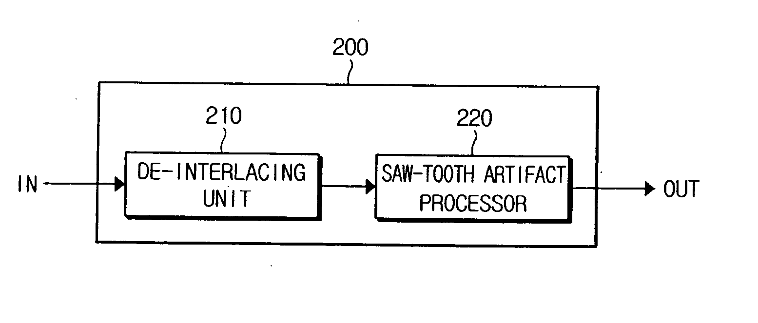
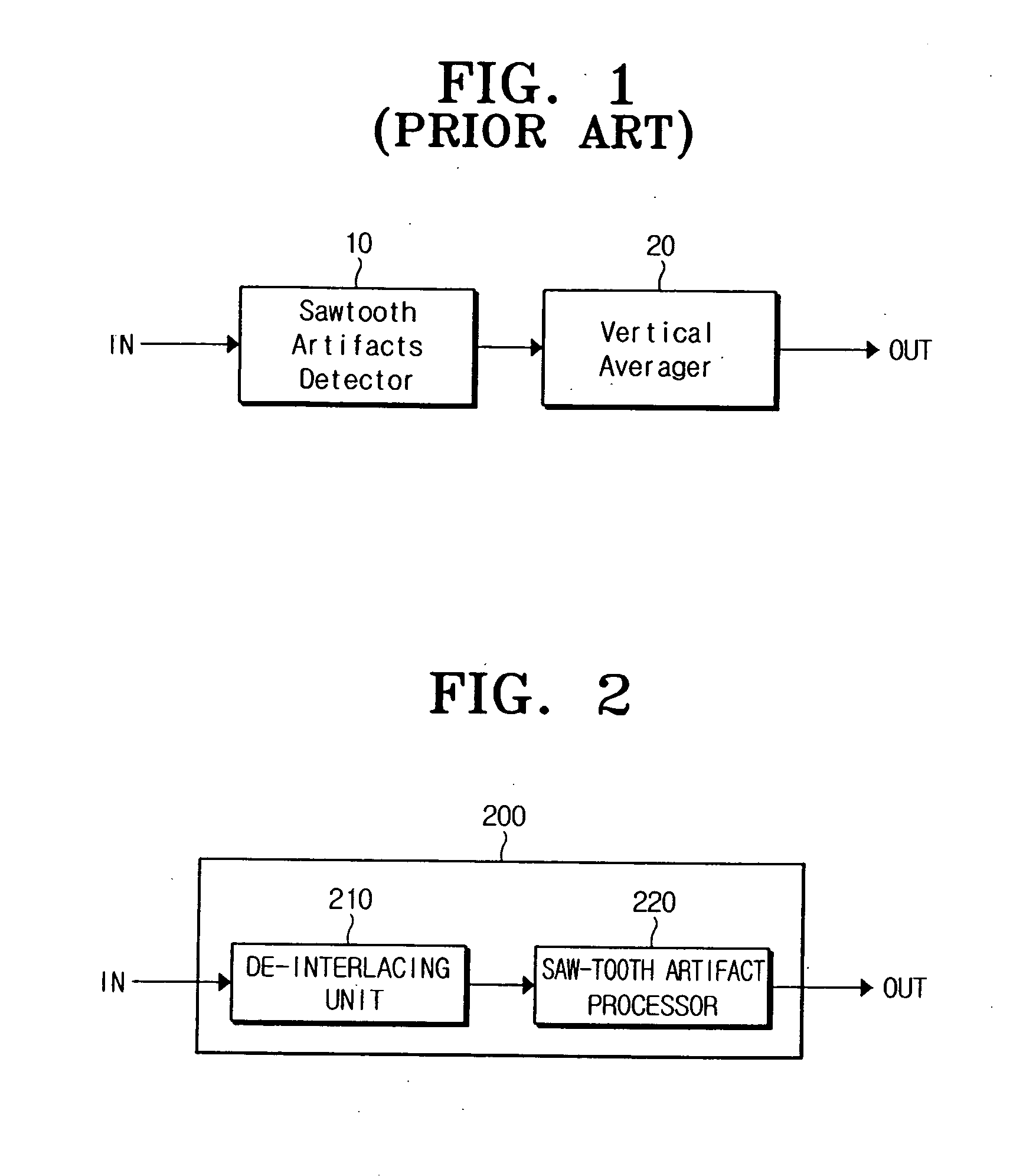
[0039]FIG. 2 is a block diagram illustrating a configuration of an apparatus 200 to enhance a distinction of image signals according to the present general inventive concept. Referring to FIG. 2, the apparatus 200 to enhance the distinction of the image signals comprises a de-interlacing unit 210 and a saw-tooth artifact processor 220. The de-interlacing unit 210 converts an input image signal using an interlaced scanning method into a de-interlaced image signal using a progressive scanning method and outputs the converted de-interlaced image signal. The saw-tooth artifact processor 220 removes saw-tooth artifacts included ...


PUM


Abstract

An apparatus to enhance a distinction of image signals and a method thereof. The apparatus includes a de-interlacing unit to de-interlace input image signals using an interlaced scanning method and to output a de-interlaced image signal using a progressive scanning method, and a saw-tooth artifact processor to remove saw-tooth artifacts based on a diffusion value and a median value of the de-interlaced image signal, the artifacts being included in the de-interlaced image signal. The saw-tooth artifacts generated when neighboring pixels have a small difference are removed, and, at the same time, the detailed components of an image are represented effectively without being lost.

Description

CROSS-REFERENCE TO RELATED APPLICATIONS [0001] This application claims the benefit under 35 U.S.C. § 119 from Korean Patent Application No. 2004-109405, filed in the Korean Intellectual Property Office on Dec. 21, 2004, the entire content of which is incorporated herein by reference. BACKGROUND OF THE INVENTION [0002] 1. Field of the Invention [0003] The present general inventive concept relates to an apparatus to enhance distinction of image signals and a method thereof. More specifically, the present general inventive concept relates to an apparatus and a method of removing saw-tooth artifacts included in de-interlaced image signals to enhance distinction of the image signals. [0004] 2. Description of the Related Art [0005] An interlaced scanning method and a progressive scanning method are used as scanning methods of an image display apparatus. The interlaced scanning method is used in TVs and the like. In the interlaced scanning method, when an image is displayed, one image fram...

Claims


Application Information

Patent Timeline
IPC IPC(8): H04N7/01H04N11/20
CPCH04N5/21H04N7/01H04N7/012
Inventor KANG, YEO-JINKWON, YOUNG-JIN
Owner SAMSUNG ELECTRONICS CO LTD
Why Eureka
Try Eureka