
Face region estimating device, face region estimating method, and face region estimating program

Active Publication Date: 2006-06-15
HONDA MOTOR CO LTD
View PDF20 Cites 62 Cited by
  • Summary
  • Abstract
  • Description
  • Claims
  • Application Information

AI Technical Summary

Benefits of technology

[0051] According to the present invention, the person's face region can be extracted from the image even when an illumination environment, for example, is changed and the image contains persons of different skin colors. According to the present invention, the amount of calculation for extracting the face region can be reduced by specifying the head region, and the face region can be appropriately extracted without recognizing the region having the same color distribution as the skin color as the face.

Problems solved by technology

That is, the technique for setting the threshold of the fixed color space had a problem of not being capable of extracting the person's face region (skin color region) because of the change in the illumination environment, for example.
The technique had another problem in that it cannot simultaneously extract each person's face region when the image contained another person with a different skin color.
However, because this technique detects the region having the same color distribution as the skin color, there is a problem in that the face region is erroneously detected.
The technique disclosed in the Japanese Published Unexamined Patent Application No. 2004-13768 has problems in that the image must have a high resolution to the extent the feature amount of the face can be extracted, and therefore the unit becomes expensive because of a camera having a high resolution and a high-capacity memory for memorizing the high resolution images, for example.

Method used


Image

  • Face region estimating device, face region estimating method, and face region estimating program
  • Face region estimating device, face region estimating method, and face region estimating program
  • Face region estimating device, face region estimating method, and face region estimating program

Examples


Embodiment Construction

[0080] Hereinafter, an embodiment of the present invention will be described with reference to the drawings.

[Construction of Face Region Estimating Device]

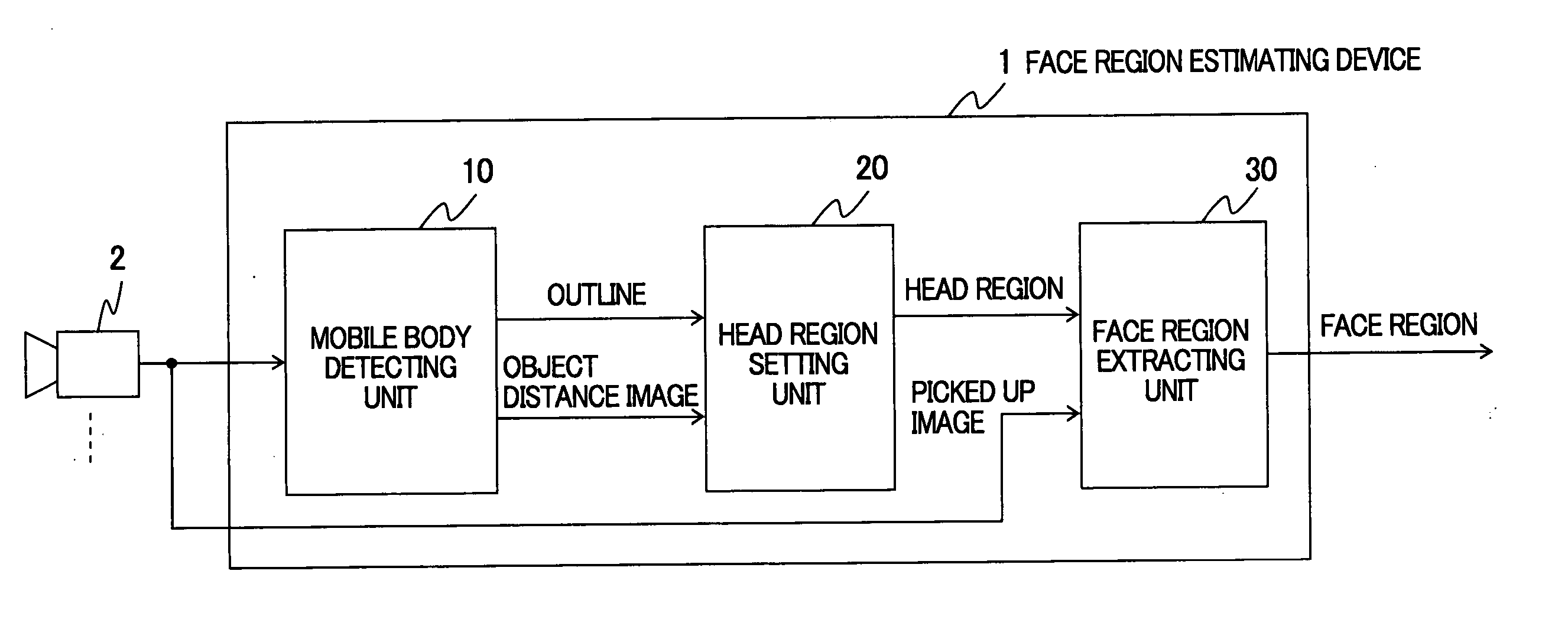
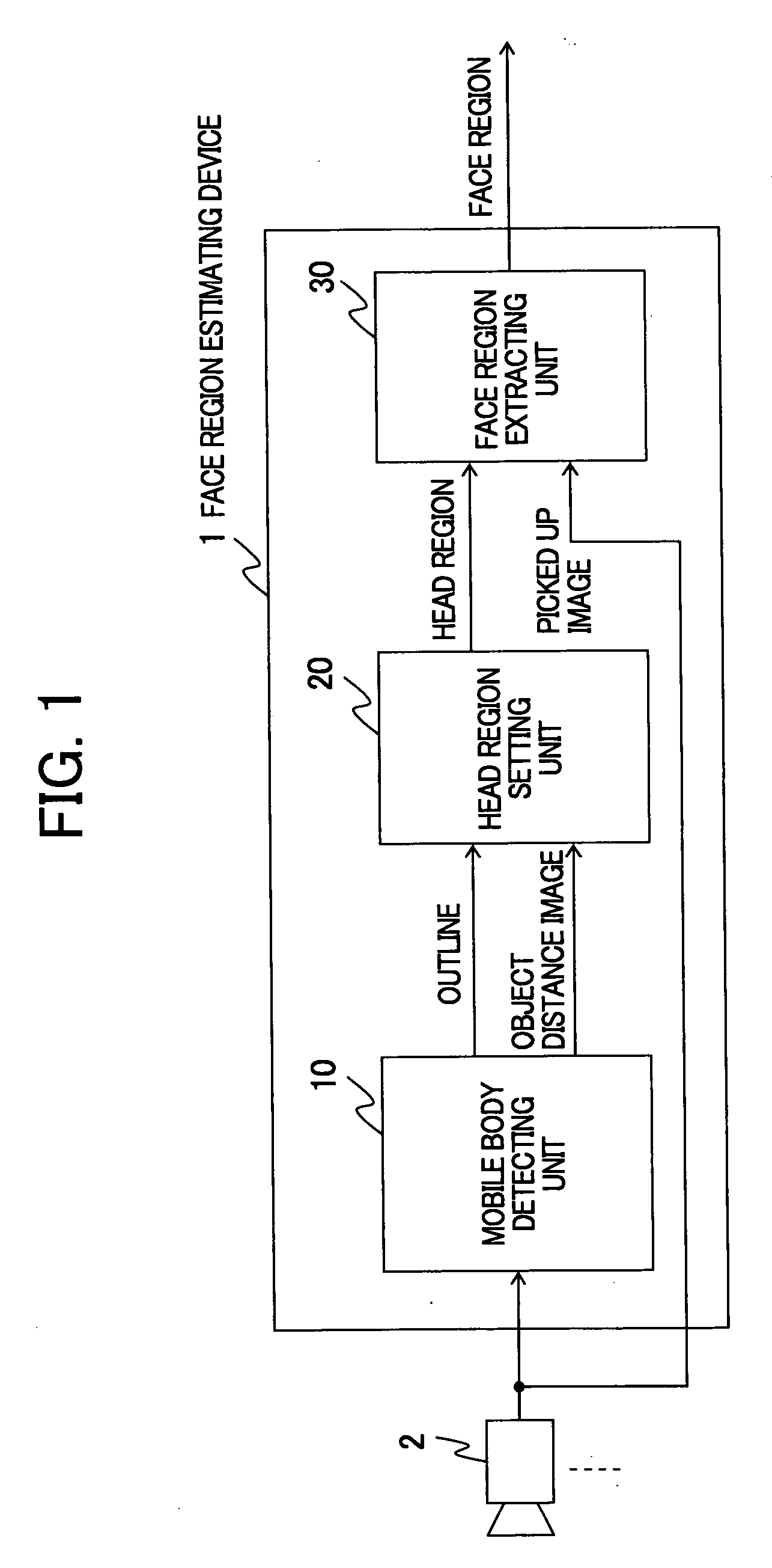
[0081]FIG. 1 is a block diagram showing an overall construction of a face region estimating device according to the present invention. As shown in FIG. 1, the face region estimating device 1 estimates a person's face region from a picked-up images taken by a plurality of cameras 2. Here, the face region estimating device 1 comprises a mobile body detecting unit 10, a head region setting unit 20 and a face region extracting unit 30.

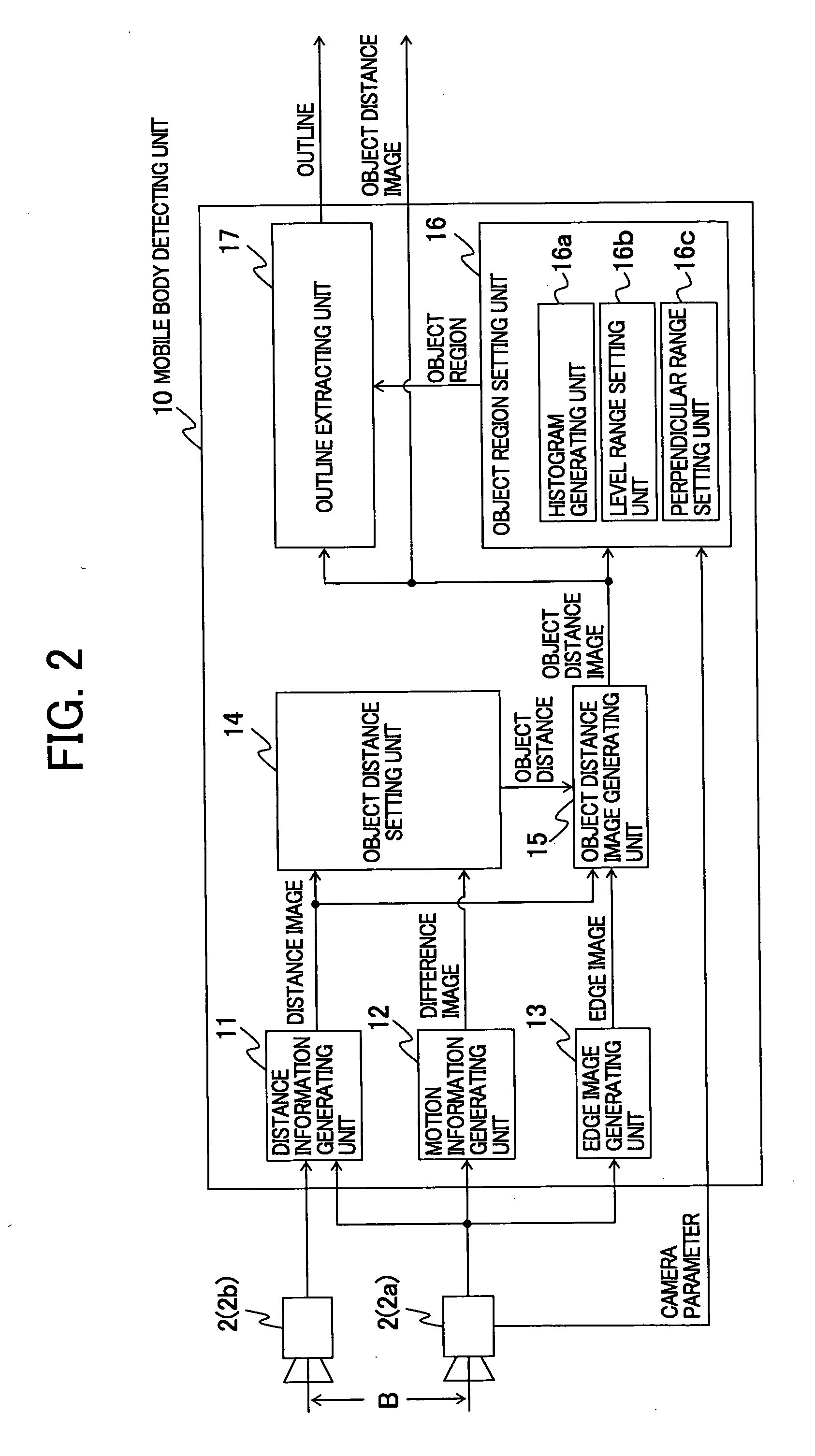
[0082] The mobile body detecting unit 10 detects a moving mobile body from the picked-up images taken by the plurality of cameras 2. Here, the mobile body detecting unit 10 extracts the outline of the mobile body from the picked-up images, generates an object distance image composed of pixels corresponding to a distance in which the mobile body exists, and outputs the outline and the object distance i...


PUM


Abstract

The invention provides a face region estimating device capable of extracting a person's face region even when an illumination environment, for example, is changed and persons with different skin colors are contained in a picked-up image taken by a camera. The face region estimating device includes: a mobile body detecting unit for extracting the outline of a mobile body from the picked-up image and for generating an object distance image composed of pixels corresponding to a distance in which the mobile body exists; a head region setting unit for setting a head region based on the pixel distribution in the object distance image corresponding to a predetermined range on the basis of a pixel position at the upper part of the outline; and a face region extracting unit for extracting the person's face region from the picked-up image based on the color distribution in the picked-up image corresponding to the head region.

Description

CROSS-REFERENCE TO RELATED APPLICATIONS [0001] This application claims the benefit of Japanese Patent Application 2004-360772 filed on Dec. 14, 2004, the disclosure of which is incorporated herein by reference. BACKGROUND OF THE INVENTION [0002] 1. Field of the Invention [0003] The present invention relates to a face region estimating device, a face region estimating method, and a face region estimating program, for estimating a region of a face of a person existing on an image taken by a camera. [0004] 2. Description of the Related Art [0005] Conventionally, a typical technique for estimating a face region (skin color region) of a person existing on an image taken by a camera such as a CCD camera was to extract from the image a region contained in a fixed range of values representing the skin color in hue, saturation and lightness (luminance) in color space to estimate the face region (skin color region). [0006] As another technique, Japanese Published Unexamined Patent Application...

Claims


Application Information

Patent Timeline
IPC IPC(8): G06K9/46G06K9/00
CPCG06K9/00201G06K9/00234G06K9/00369G06T7/0081G06T7/2053G06T2207/20148G06T2207/30201G06T7/11G06T7/254G06T7/136G06V20/64G06V40/162G06V40/103
Inventor HIGAKI, NOBUO
Owner HONDA MOTOR CO LTD
Learn More