
Dynamic sub-carrier assignment in OFDM systems

a subcarrier and dynamic technology, applied in the field of digital radio communication systems, can solve the problems of converting transmission power from the remaining unused unacceptable subcarriers, and achieve the effect of improving the efficiency of the communication system, high transmission rate and high efficiency

Inactive Publication Date: 2006-06-15
BLACKBERRY LTD
View PDF8 Cites 69 Cited by
  • Summary
  • Abstract
  • Description
  • Claims
  • Application Information

AI Technical Summary

Benefits of technology

[0010] The method provides improved efficiency of a communication system by allowing sub-carriers having a high signal to interference ratio to use a higher transmission rate. Sub-carriers having a low signal to interference ratio can be used for less sensitive traffic, or their transmission power can be diverted to sub-carriers having a high signal to interference ratio.

Problems solved by technology

The base station may allocate for low sensitivity data transmission sub-carriers within some of the unacceptable sub-carriers, may allocate for data transmission at a low transmission rate sub-carriers within some of the remaining unacceptable sub-carriers, and may divert transmission power from the remaining unused unacceptable sub-carriers to other sub-carriers.

Method used


Image

  • Dynamic sub-carrier assignment in OFDM systems
  • Dynamic sub-carrier assignment in OFDM systems
  • Dynamic sub-carrier assignment in OFDM systems

Examples


Embodiment Construction

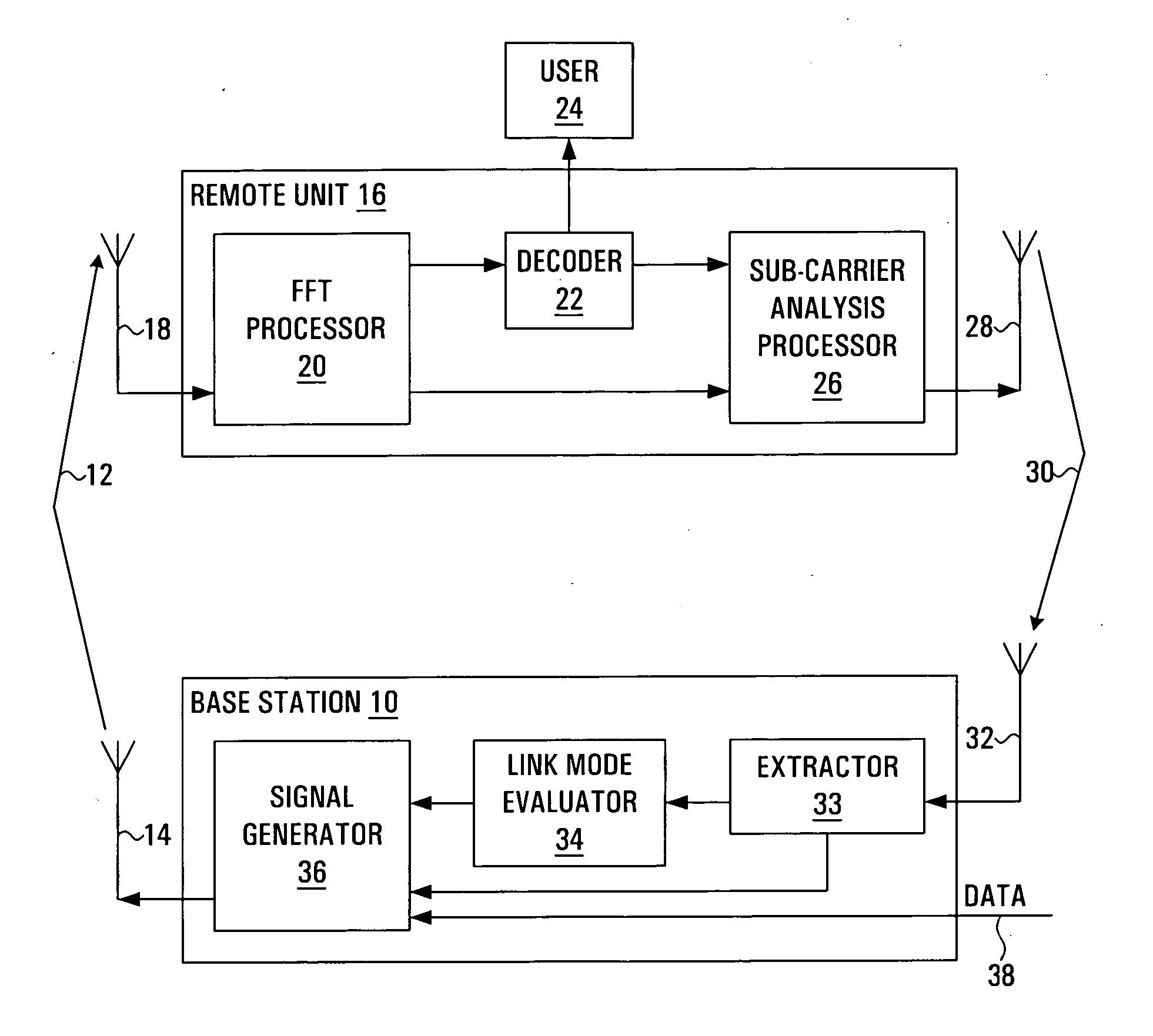
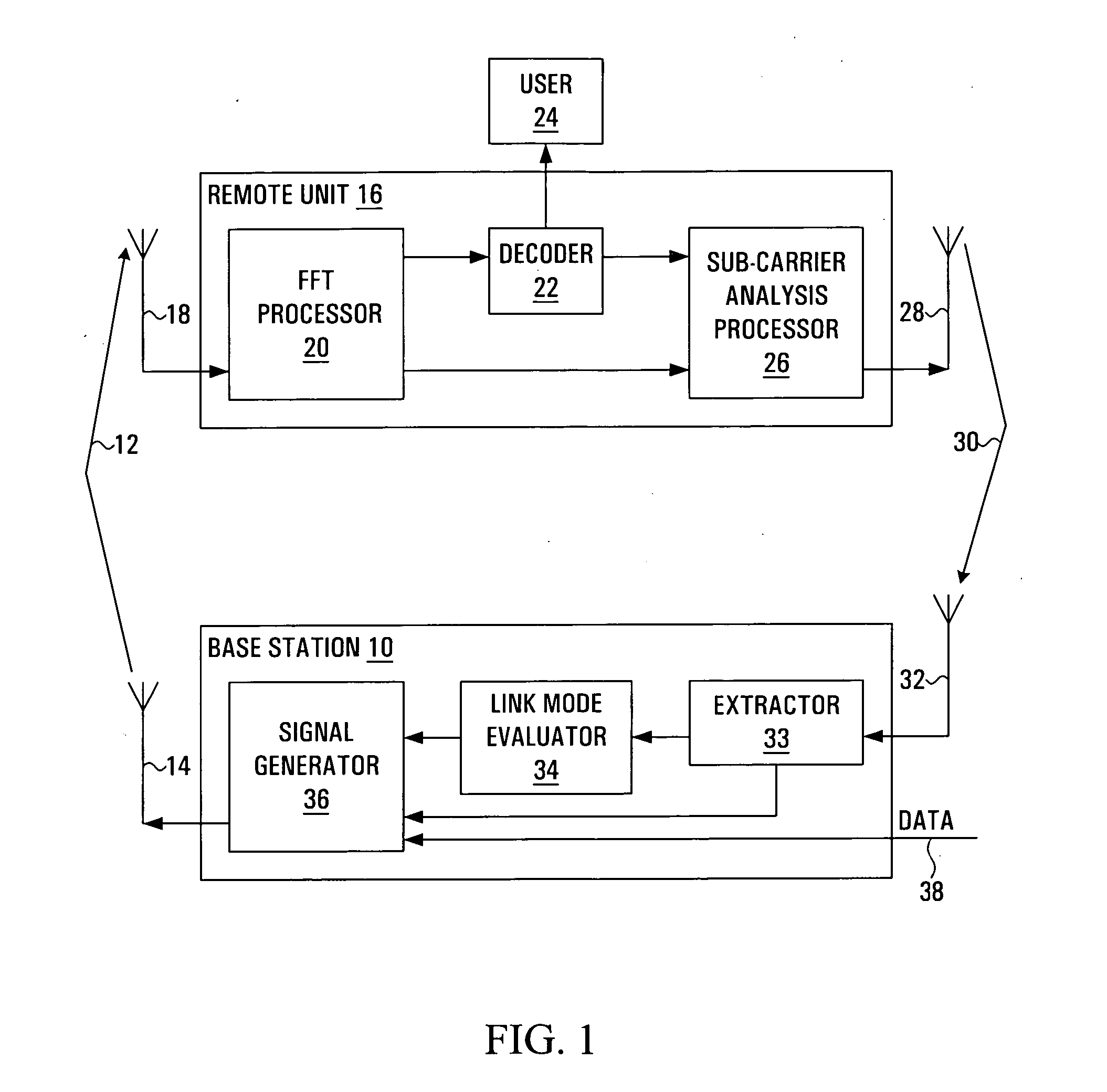
[0019] Referring to FIG. 1, a portion of a radio communication system is shown. The radio communication system employs a plurality of sub-carriers to transmit traffic from a base station 10 to a remote unit 16. For example, the radio communication system may employ Orthogonal Frequency Division Multiplexing. A signal generator 36 within the base station 10 generates a signal 12. The signal is transmitted through a base station transmitting antenna 14. Each sub-carrier carries data encoded with a Link Mode. A Link Mode is a set of at least one transmission parameter, such as a modulation level, a coding rate, a symbol rate, a transmission power level, antenna directional parameters, or space-time coding parameters. The signal 12 propagates along a forward link to the remote unit 16, where it is received at a remote unit receiving antenna 18 as a received signal. A Fast Fourier Transform (FFT) processor 20 within the remote unit 16 separates the received signal into a plurality of sub...


PUM


Abstract

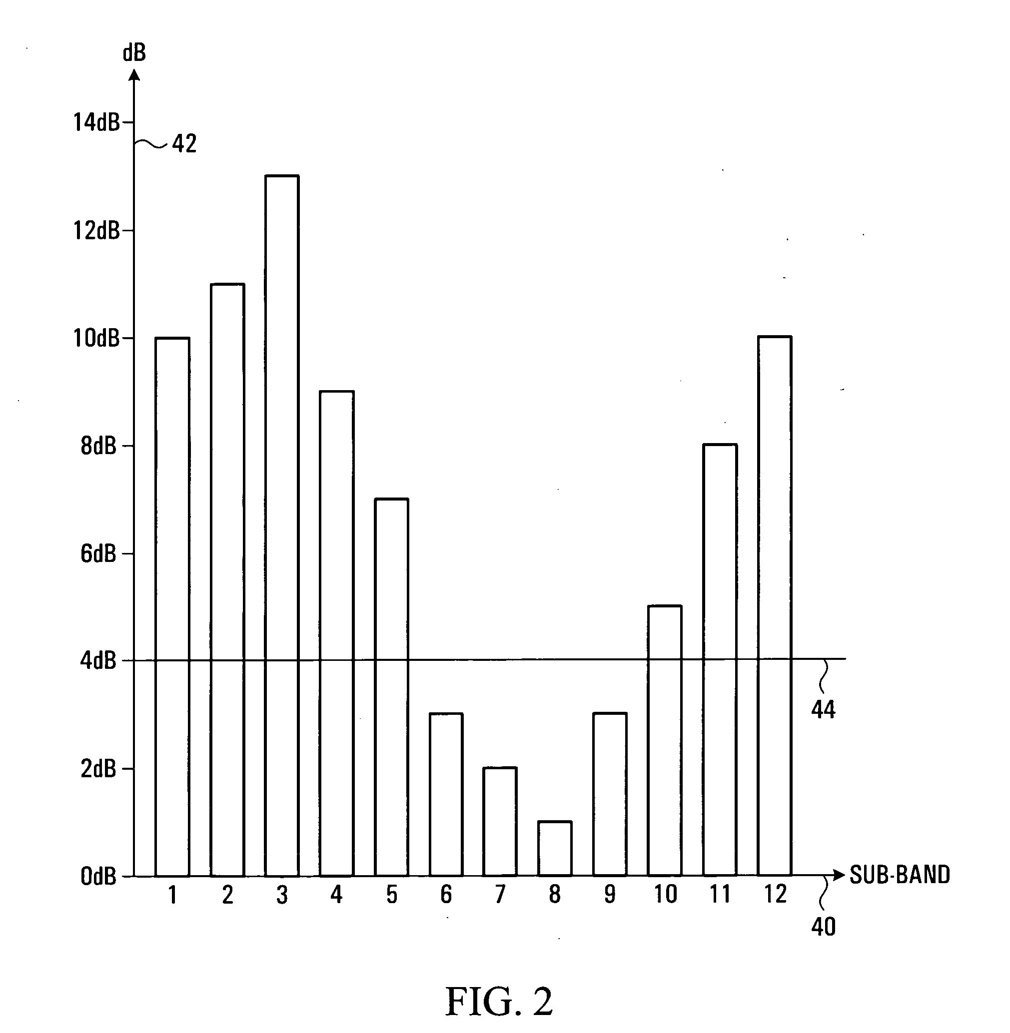
A method and apparatus are provided for selecting and signalling the identity of sub-carriers to be used for transmission of data in a radio communication system, and for using other sub-carriers. A remote unit determines which sub-carriers are acceptable for use in data transmission by comparing the signal to interference ratio of each sub-carrier with a threshold. A sequence of numbers is generated using one set of values to identify acceptable sub-carriers and another set of values to identify unacceptable sub-carriers. The sequence of numbers is transmitted to a base station. The average signal to interference ratio of sub-carriers whose signal to interference ratio was above the threshold can also be transmitted to the base station, thereby allowing the base station to determine an optimum set of transmission parameters for use only in the acceptable sub-carriers. Alternatively, the remote unit can determine the optimum set of transmission parameters itself for transmission to the base station. As yet another alternative, the remote unit can determine an optimum Link Mode for each acceptable sub-carrier, and use a reference to the Link Modes as the set of values identifying acceptable sub-carriers. The base station transmits data over the acceptable sub-carriers at the optimum Link Mode or Link Modes. The base station may use some of the unacceptable sub-carriers for transmission of low sensitivity data at the optimum Link Mode, and may use some of the unacceptable sub-carriers for transmission of data at a lower Link Mode. The transmission power of any unused unacceptable sub-carriers can be diverted to other sub-carriers.

Description

CROSS-REFERENCE TO RELATED APPLICATIONS [0001] This application is a divisional of application Ser. No. 10 / 737,772 filed Dec. 18, 2003 which, in turn, is a divisional of application Ser. No. 09 / 072,704 filed Sep. 29, 2000.FIELD OF THE INVENTION [0002] This invention relates to digital radio communication systems employing multiple sub-carriers, and more particularly to dynamic use of sub-carriers within such systems. BACKGROUND OF THE INVENTION [0003] In a digital radio communication system a base station transmits a signal at a transmission rate to a remote unit through a radio channel having channel characteristics, such as an attenuation. The signal is transmitted using transmission parameters, such as a modulation level and a coding rate. The transmission rate depends on the transmission parameters. The transmission parameters are constrained by an acceptable bit error rate and by a signal to interference ratio of the signal, the latter varying in time with the channel character...

Claims


Application Information

Patent Timeline
Patent Type & Authority Applications(United States)
IPC IPC(8): H04J11/00H04W72/04H04W72/08
CPCH04L27/2608H04W72/0453H04W72/08H04L5/0044H04W72/54
Inventor HASHEM, BASSAM M.STEER, DAVID G.PERIYALWAR, SHALINI S.
Owner BLACKBERRY LTD
Learn More