
Actuating magnet

Inactive Publication Date: 2006-06-08
VOITH TURBO SCHARFENBERG
View PDF12 Cites 3 Cited by
  • Summary
  • Abstract
  • Description
  • Claims
  • Application Information

AI Technical Summary

Benefits of technology

[0006] The object of the present invention, therefore, is to refine an actuating magnet of the aforementioned type which ensures reliable locking and unlocking of the actuating means for the actuating magnet.
[0008] When according to the prior art a spring has been used to hold the actuating means for the actuating magnet in a desired position, this object of the invention is then achieved by a locking magnet which allows the actuating means to be reliably locked and unlocked. A significant advantage in this case is that the actuating means is not moved from its position, even when severe vibrations or accelerations act on the actuating magnet. The use of a latching means having a locking magnet for locking and unlocking the actuating means thus guarantees reliable latching of the actuating means in a desired position. According to the invention, before the actuating means is actuated the latching device is released by use of the locking magnet so that the actuating means for the actuating magnet can be freely moved.
[0010] As mentioned previously, before the actuating element is moved it must first be unlocked by actuating the locking magnet. Of course, a corresponding circuit may be used here to ensure the required switching delay between the actuating magnet and locking element. However, the locking magnet according to the invention is preferably designed in such a way that it does not respond until both magnets are simultaneously activated and / or deactivated. This can be achieved, for example, by a differing number of inductive windings for both magnets, or by differing masses to be moved, thus, for example, by reducing the mass of the actuating means for the locking magnet. The same result is obtained by designing the locking magnet in a smaller basic size than the actuating magnet. This has the advantage that the locking magnet not only responds more quickly than the actuating magnet following a switching signal, but can also be compactly situated on or inside the actuating magnet. Such a design generally has the result that, without costly and sensitive electronic circuits, when a switching signal is simultaneously sent to both magnets first the locking magnet and then the actuating magnet responds, and, therefore, first the lock is released and then the actuating means for the actuating magnet is moved.
[0011] Thus, the actuating magnet and the locking magnet may be designed so that they can be activated and / or deactivated via the same switching signal. It is also conceivable to activate and deactivate both magnets via the same power source. Both embodiments allow a much smaller and more compact design, and are also more economical than comparable designs known from the prior art.
[0013] This embodiment has several advantages. Specifically, it allows the latching means which latches the actuating means to be strictly separated from the locking magnet which initiates this latching. In particular for high-load actuating magnets, this prolongs the operating life of the actuating magnet, since the forces from the actuating magnet do not act directly on the sensitive locking magnet, but instead act on a preferably robust locking component, in this case the locking arm. The previously mentioned embodiment also allows a compact arrangement of the locking magnet, since an appropriate design of the locking arm allows practically any configuration and position of the locking magnet. Lastly, the use of a rotatably mounted locking arm allows very small locking magnets to be employed, which by their nature are less powerful than larger models. However, since the known lever principles act via the rotatably mounted locking arm, even for large locking and unlocking forces it is possible to use a very small locking magnet having a correspondingly large lift or working path.

Problems solved by technology

However, it has been shown that motions of the actuating means can occur in such actuating magnets even when the magnet is deactivated.
This unwanted motion of the actuating element may result in serious accidents and must therefore be avoided.

Method used


Image

  • Actuating magnet
  • Actuating magnet
  • Actuating magnet

Examples


Embodiment Construction

[0019] In the following description, identical parts having equivalent action are provided with the same reference numbers.

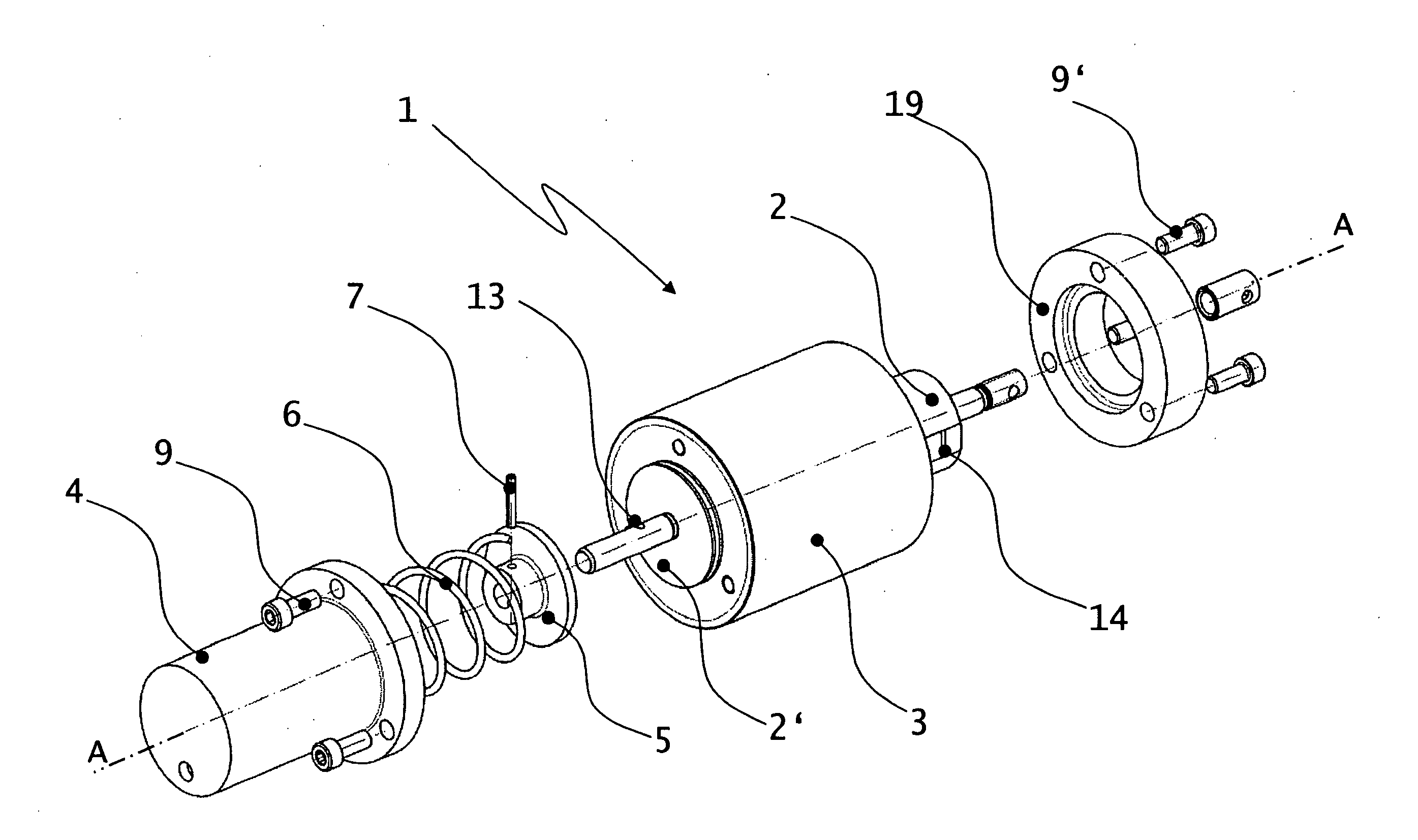
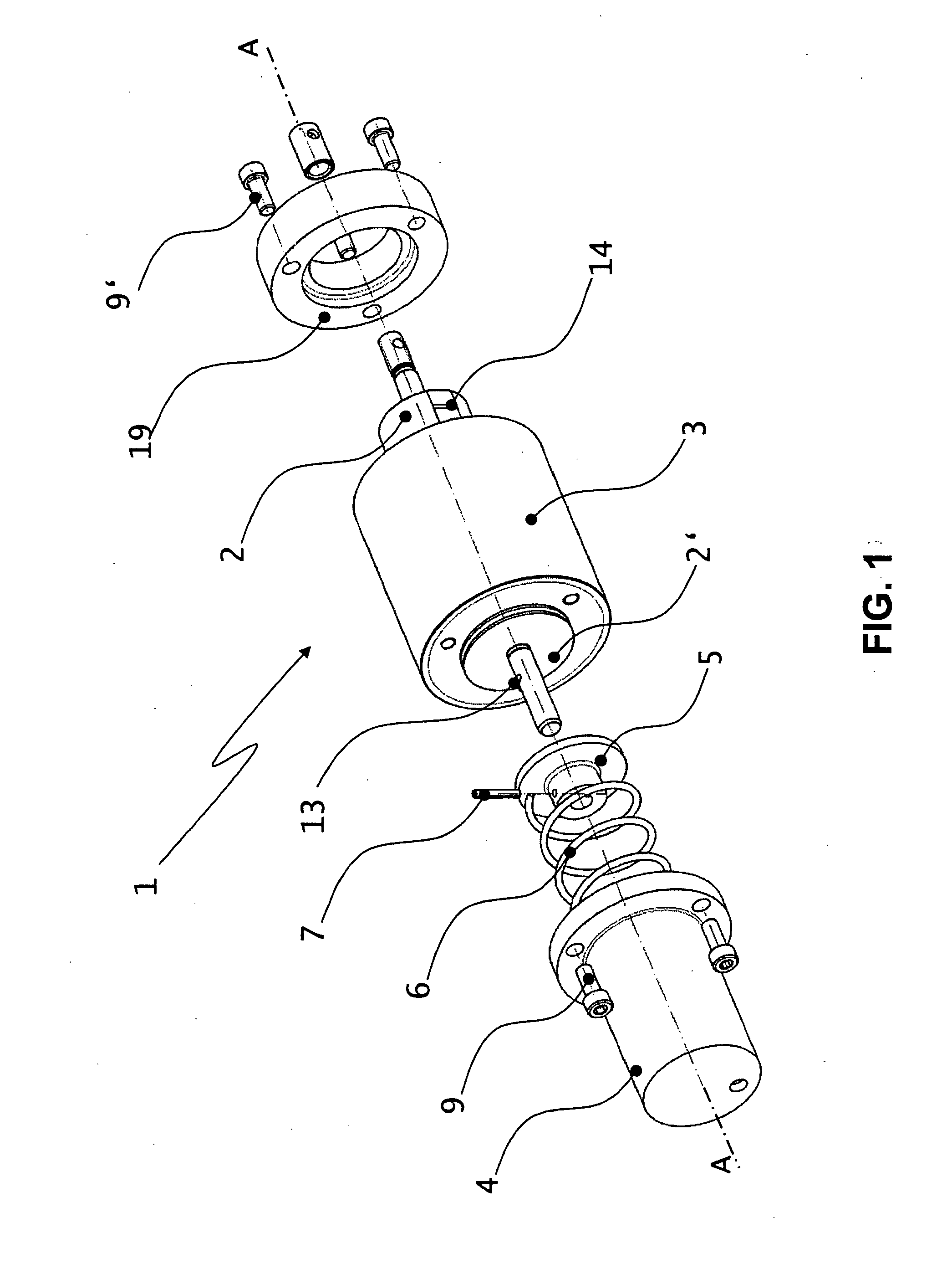
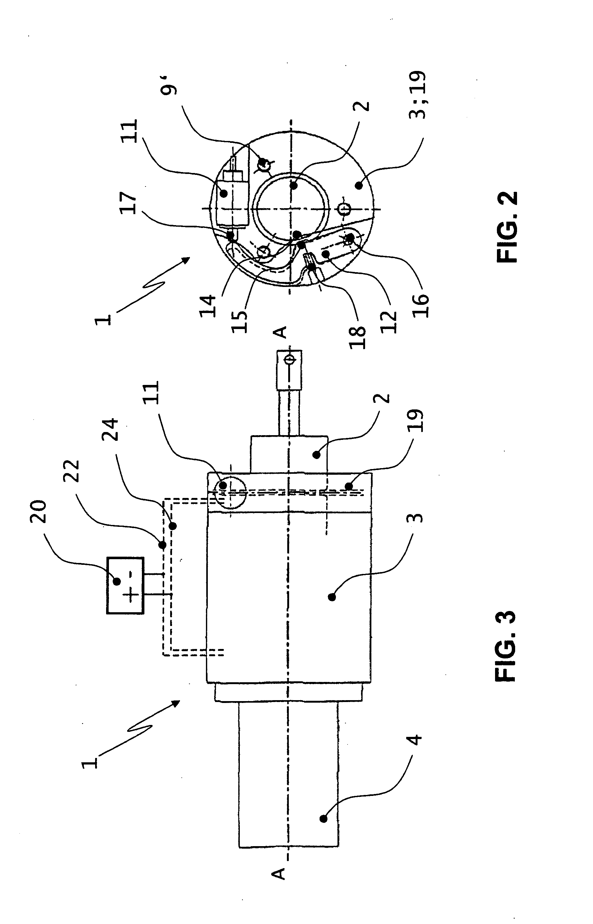
[0020]FIG. 1 shows a detailed isometric exploded illustration of the actuating magnet 1. A magnet housing 3 is illustrated which contains an actuating means 2, 2′—in this case, explicitly an anchor—that is movably mounted along an axis A-A. The internal structure of this anchor-housing apparatus corresponds to the design of a standard electromagnet known from the prior art. In this case the actuating magnet 1 is designed as a simple solenoid; in other words, electrical de-energizing or energizing enables a lifting motion in only one direction, whereas the lifting motion in the opposite direction is produced by an externally applied elastic force. To this end, the actuating magnet 1 has a spring cup 4 which is fastened to the magnet housing 3 by screws 9. This spring cup contains a pressure spring 6 which is supported against the movably mounted actuating means ...


PUM


Abstract

An actuating magnet is disclosed comprising an actuating means (2) for exerting a tensile or pressure force on a target element that is to be moved, switched, or latched or unlatched, and comprising a latching means for latching the actuating means (2) in a desired position, the latching means having a locking magnet (11) for locking and unlocking the actuating means (2).

Description

BACKGROUND OF THE INVENTION [0001] I. Field of the Invention [0002] The invention relates to an actuating magnet comprising an actuating means for exerting a tensile or pressure force on a target element that is to be moved, switched, or latched or unlatched, and comprising a latching means for latching the actuating means in a desired position. [0003] II. Background and Prior Art [0004] The term “target element” is understood to mean all components of a device, such as electrical switches, latching bolts which are inserted into corresponding latching grooves, swivel bearings, and in particular latching devices for coupling arrangements for rail vehicles having at least one pivotable coupling head, and components similar thereto, which are to be moved, swiveled, switched, or latched or unlatched. [0005] Such actuating magnets are known in the prior art. They find application, for example, in coupling arrangements for rail vehicles, and in this case allow, for example, the targeted l...

Claims


Application Information

Patent Timeline
IPC IPC(8): E05C19/16H01F7/124H01F7/16
CPCH01F7/124H01F7/1607Y10T292/11
Inventor KRAUSE, REINER
Owner VOITH TURBO SCHARFENBERG
Learn More