
Precision geolocation system and method using a long baseline interferometer antenna system

Inactive Publication Date: 2006-06-01
SIERRA NEVADA CORP
View PDF7 Cites 77 Cited by
  • Summary
  • Abstract
  • Description
  • Claims
  • Application Information

AI Technical Summary

Benefits of technology

[0007] The very long baseline geolocation system and method of the present invention provides geolocation accuracy using a single platform equivalent to that of multiple observer systems. Geolocation accuracies have been observed with the present invention on the order a 100 foot circular error probability for an emitter at a distance of 100 nautical miles, with observation times typically ranging from 1 to 5 minutes. Of course, the system can provide less precise measurements in shorter times.
[0009] simple installation, requiring a small number ESM / GSM antenna elements that can be located at the extremities of the platform,

Problems solved by technology

Of course, the system can provide less precise measurements in shorter times.

Method used


Image

  • Precision geolocation system and method using a long baseline interferometer antenna system
  • Precision geolocation system and method using a long baseline interferometer antenna system
  • Precision geolocation system and method using a long baseline interferometer antenna system

Examples


Embodiment Construction

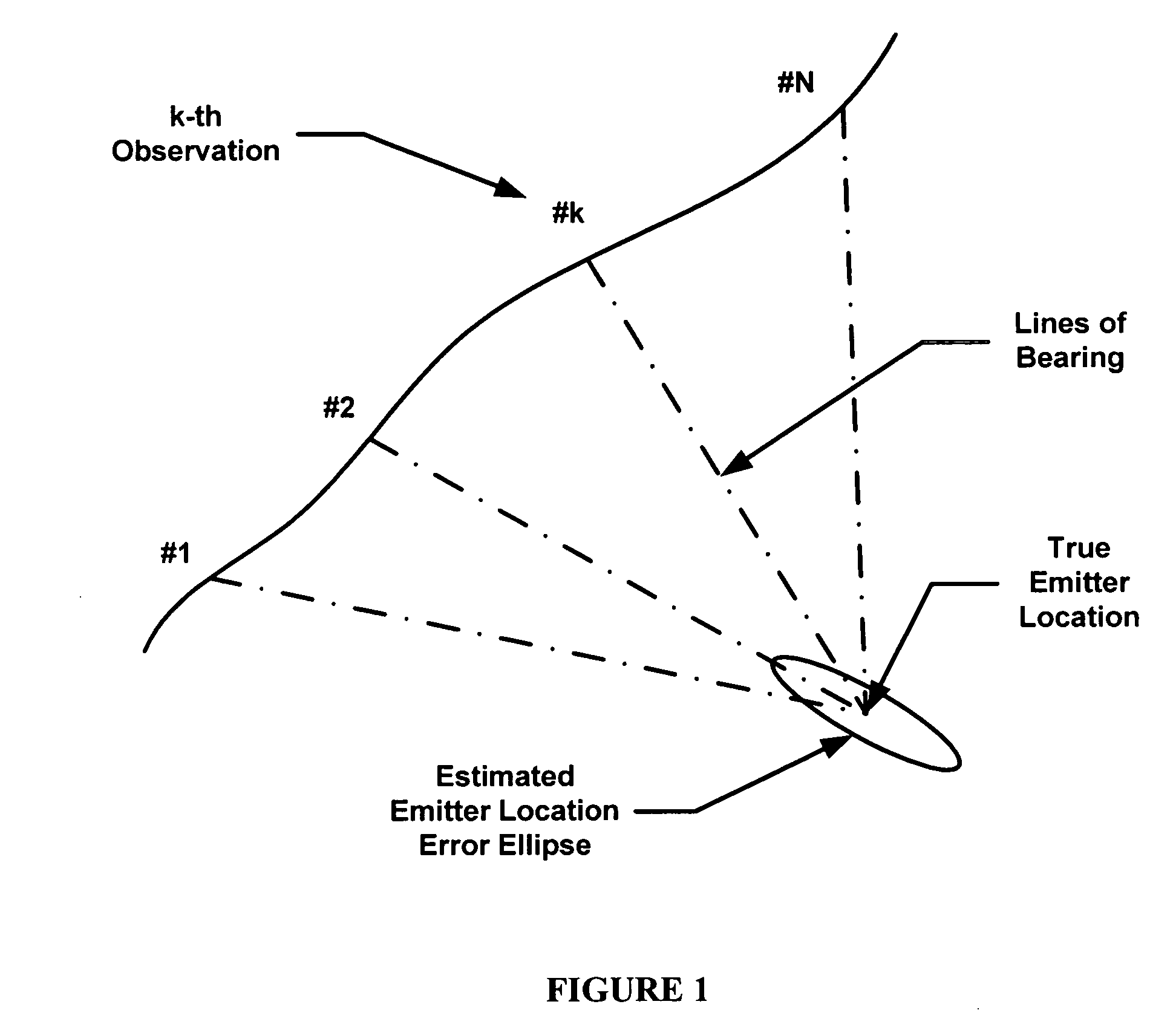
[0033] A single observer geolocation method can be illustrated as an equivalent triangulation process, as shown in the simplified two dimensional view of FIG. 1. A platform moving along a measurement path from point #1 to point #N makes multiple observations of the radio frequency signals transmitted by an emitter whose location is sought. From the observations, the system computes lines of bearing between the measurement location and the emitter. The lines of bearing should intersect at the emitter location. However, due to measurement noise, the lines of bearing almost never truly intersect at a single point. Statistical methods are commonly used to estimate the emitter location, which includes an estimate of the uncertainty of the emitter location indicated by location ellipses or circles. These ellipses or circles are related to the Elliptical Error Probability (EEP) or Circular Error Probability (CEP) which defines elliptical or circular regions with the minimum area or volume ...


PUM


Abstract

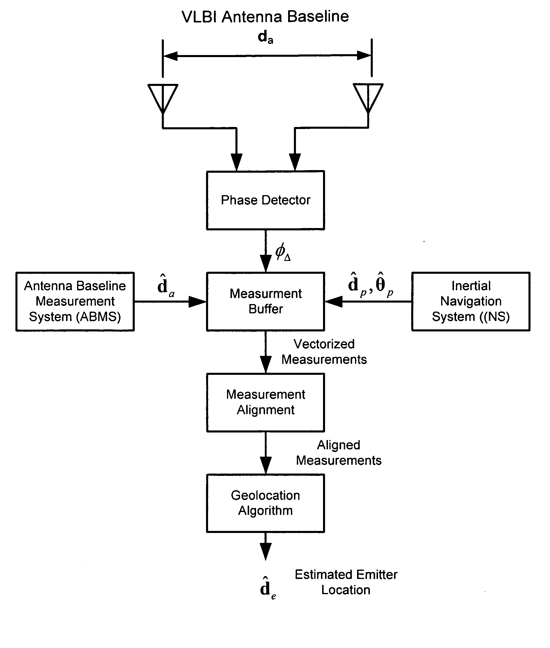
A long baseline interferometer antenna system and method for determining the location of an emitter. The long baseline interferometer antenna system comprises a first antenna, a second antenna, an inertial navigation system, an antenna baseline measurement system, a multi-channel receiver and a processor. The first and second antenna elements are positioned on a platform and are both configured to receive signals from the emitter. The first and second antenna elements form a long baseline antenna pair. The inertial navigation system measures the platform position and attitude; and the antenna baseline measurement system measures the antenna baseline vector between the first and second antenna elements. The multi-channel receiver measures the differential phase between antenna pairs, and the processor computes the emitter location. Additional antenna elements can be included and some can be configured as squinted beam pair and make use of amplitude difference of arrival measurements.

Description

RELATED APPLICATIONS [0001] This application claims the benefit of U.S. Provisional Application Ser. No. 60 / 600,715, filed Aug. 11, 2004, the full disclosure of which is hereby expressly incorporated by reference.TECHNICAL FIELD OF THE INVENTION [0002] The present invention relates to methods and systems for precision geolocation of an emitter whose location is sought by a moving platform monitoring signals transmitted by the emitter. More specifically, the invention relates to precision geolocation by a platform having a long baseline interferometer antenna system that monitors electromagnetic signals transmitted by the emitter. BACKGROUND OF THE INVENTION [0003] Multiple observer and single observer geolocation systems that monitor an emitter's signals to determine its location are known in the art. The monitoring system makes multiple observations of the emitter signal at multiple locations and measures characteristics of the received signals and processes these measurements to p...

Claims


Application Information

Patent Timeline
IPC IPC(8): G01S5/02G01S3/02G01S19/11
CPCG01S3/46G01S5/04
Inventor KOLANEK, JAMESCARLSEN, ERIC
Owner SIERRA NEVADA CORP
Learn More