
Foot massaging apparatus

Inactive Publication Date: 2006-05-25
MATSUSHITA ELECTRIC WORKS LTD
View PDF10 Cites 6 Cited by
  • Summary
  • Abstract
  • Description
  • Claims
  • Application Information

AI Technical Summary

Benefits of technology

[0008] It is therefore an object of the present invention to provide a foot massaging apparatus which can solve the above conventional problems.
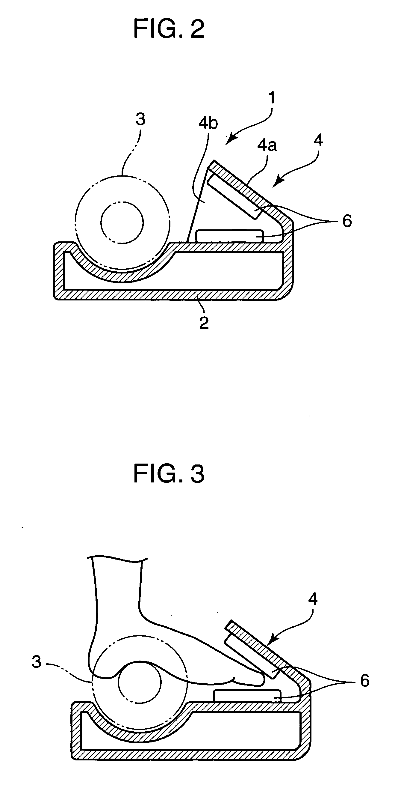
[0009] It is another object of the present invention to provide a foot massaging apparatus capable of repeatedly performing a pressing operation for the foot or other leg region of a user using a rotatable roller unit and a massaging operation for the toe region of the user to prevent the user from getting bored. According to an aspect of the present invention, a foot massaging apparatus is provided with a housing for supporting user's foot, a rotatable roller unit mounted on the housing. Further, a toe-region pinching unit is mounted on the housing and located in front of the rotatable roller unit. The toe-region pinching unit has an air cell adapted to be inflated and deflated, respectively, by charging and discharging air thereto and therefrom, so as to repeatedly pinch the toe region of the user's foot.

Problems solved by technology

While the above conventional foot massaging apparatuses are designed to allow user's feet or other leg region to repeatedly receive a pressing operation from the rotatable roller unit, the pressing operation provides only mechanical rotational stimulations, and thereby a user is apt to get bored easily.
Moreover, these apparatuses cannot perform a massaging operation for the toe region of user's foot.
Thus, there remain problems to be improved.

Method used


Image

  • Foot massaging apparatus
  • Foot massaging apparatus
  • Foot massaging apparatus

Examples


first embodiment

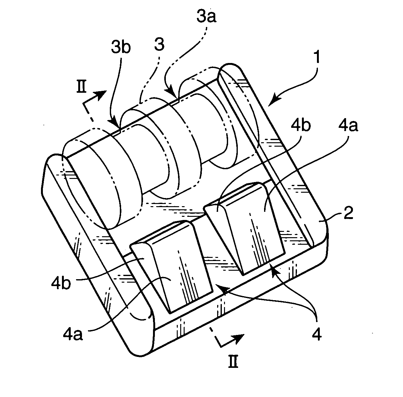
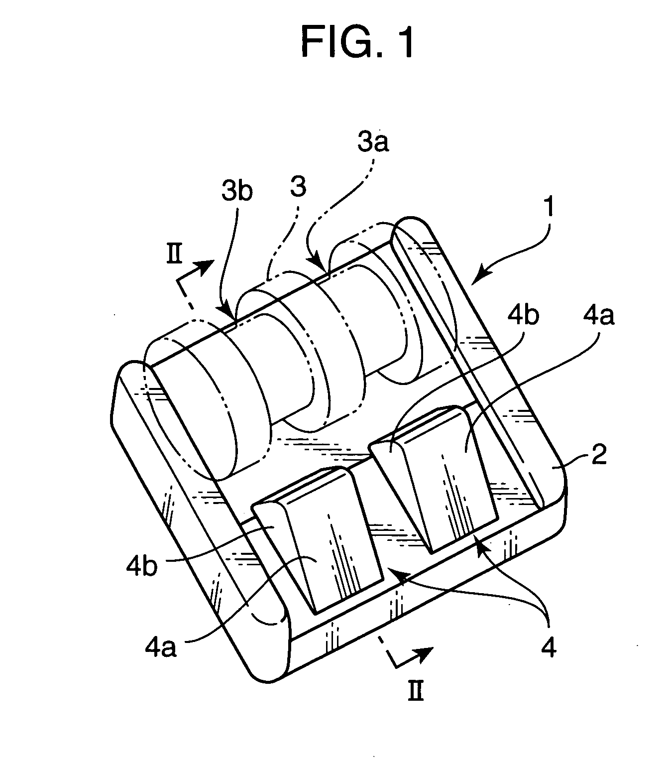
[0039]FIG. 1 is a perspective external view showing a foot massaging apparatus according to a first embodiment of the present invention, and FIG. 2 is a sectional view taken along the line II-II in FIG. 1.

[0040] This foot massaging apparatus 1 comprises a housing 2 for supporting the foot of a user, a rotatable roller unit 3, and a toe-region pinching unit 4. The rotatable roller unit 3 and the toe-region pinching unit 4 are mounted on a top surface of the housing 2. The rotatable roller unit 3 is located in a rear region of the housing 2, and the toe-region pinching unit 4 is located in front of the rotatable roller unit 3.

[0041] The rotatable roller unit 3 may have any suitable structure capable of repeatedly performing a pressing operation for the foot or feet of a user. For example, the rotatable roller unit 3 may be one selected from conventional rotatable roller units including the rotatable roller units as disclosed in the aforementioned Patent Publications 1 or 2. The rota...

second embodiment

[0045]FIG. 4 is a top plan view showing a foot massaging apparatus according to a second embodiment of the present invention, and FIG. 5 is a front perspective view showing a toe-region pinching unit of this foot massaging apparatus. In this embodiment and after-mentioned embodiments, the same component as that in the first embodiment is defined by the same reference numeral.

[0046] In this foot massaging apparatus 11, a rotatable roller unit 3 and a pair of toe-region pinching units 14 are disposed on a housing 12 for supporting the foot or feet of a user, in the same positional relationship as that in the first embodiment. The rotatable roller unit 3 has the same structure as the rotatable roller unit in the first embodiment.

[0047] In this embodiment, the pair of toe-region pinching units 14 are formed separately from the housing 12, and disposed, respectively, on right and left regions of a top surface of the housing 12 in such a manner that each of the toe-region pinching units...

third embodiment

[0052]FIG. 6 is a top plan view showing a foot massaging apparatus according to a third embodiment of the present invention, and FIG. 7 is a front perspective view showing a toe-region pinching unit of this foot massaging apparatus.

[0053] In this foot massaging apparatus 21, a rotatable roller unit 3 and a pair of toe-region pinching units 24 are disposed on a housing 22 for supporting the foot or feet of a user, in the same positional relationship as that in the first embodiment. The rotatable roller unit 3 has the same structure as the rotatable roller unit in the first embodiment.

[0054] In this embodiment, the pair of toe-region pinching units 24 are formed separately from the housing 22, and disposed, respectively, on right and left regions of a top surface of the housing 22 in such a manner that each of the toe-region pinching units 24 is slidably moved independently in a forward / backward direction of the housing 22. The detailed structures of the toe-region pinching unit 24 ...


PUM


Abstract

Disclosed is a foot massaging apparatus, which comprises a housing for supporting user's foot, a rotatable roller unit mounted on the housing, and a toe-region pinching unit mounted on the housing and located in front of the rotatable roller unit. The toe-region pinching unit has an air cell adapted to be inflated and deflated, respectively, by charging and discharging air thereto and therefrom, so as to repeatedly pinch the toe region of the user's foot. The foot massaging apparatus can repeatedly perform a pressing operation for the foot or other leg region using the rotatable roller unit and a massaging operation for the toe region to prevent the user from getting bored.

Description

BACKGROUND OF THE INVENTION [0001] 1. Field of the Invention [0002] The present invention relates to a foot massaging apparatus for massaging the foot or calf of a user. [0003] 2. Description of the Related Art [0004] Heretofore, there have been known various foot massaging apparatuses as shown, for example, in FIG. 26 [see Japanese Patent Laid-Open Publication No. 15-052781 (Patent Publication 1)] and FIG. 27 [see Japanese Patent Laid-Open Publication No. 11-239595 (Patent Publication 2)]. [0005] In the conventional foot massaging apparatus illustrated in FIG. 26, a rotatable roller unit 101 having two grooves 102 for receiving therein right and left feet of a user is mounted to a foot-supporting housing 100 in a rotatably driven manner. Each of the grooves 102 has a width changing in a circumferential direction of the rotatable roller unit 101, and includes a plurality of pressing fingers 103 disposed on both sides thereof. When a user inserts his / her foot into the groove 102, the...

Claims


Application Information

Patent Timeline
IPC IPC(8): A61H15/00
CPCA61H9/0078A61H15/0078A61H2015/0014A61H2205/12
Inventor MIZUUCHI, AKIHIRO
Owner MATSUSHITA ELECTRIC WORKS LTD
Learn More