
Method and system for synthetic aperture sonar

a synthetic aperture and sonar technology, applied in the field of synthetic aperture sonar, can solve the problems of limited physical array length, limited performance of conventional active sonar systems, and inability to prevent acoustic propagation to long ranges

Active Publication Date: 2006-05-25
RAYTHEON CO
View PDF2 Cites 26 Cited by
  • Summary
  • Abstract
  • Description
  • Claims
  • Application Information

AI Technical Summary

Benefits of technology

[0013] The present invention provides a method and system for synthetic aperture sonar having an improved ability to provide position and orientation estimates of a moving sonar array as it moved through the water.

Problems solved by technology

However, physical array length is often limited by a size of a platform to which the receive array is attached.
Furthermore, high acoustic frequencies attenuate rapidly in the water, preventing acoustic propagation to long ranges.
As a result, conventional active sonar systems are limited in performance by receive array length constraints and by acoustic frequency constraints.
It is known that more rapid movement of the receive array results in formation of grating lobes.
However, the IMU and the other ancillary equipment are costly, and require space and power that are at a premium for undersea receive arrays.
This technique does not obtain precise track estimates for motion in all six degrees of freedom.

Method used


Image

  • Method and system for synthetic aperture sonar
  • Method and system for synthetic aperture sonar
  • Method and system for synthetic aperture sonar

Examples


Embodiment Construction

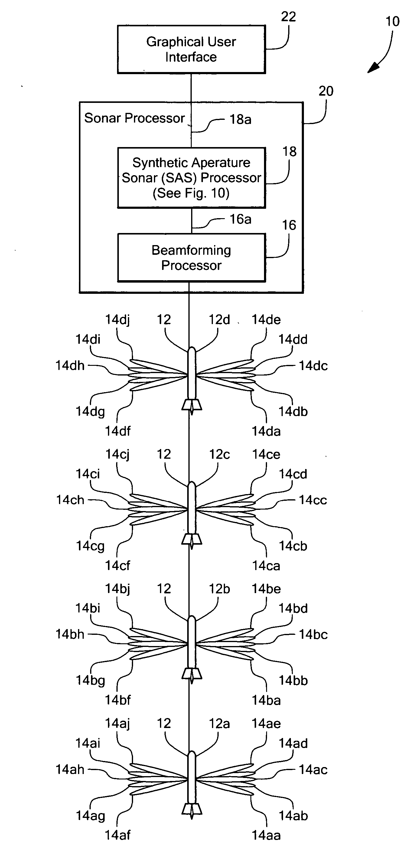
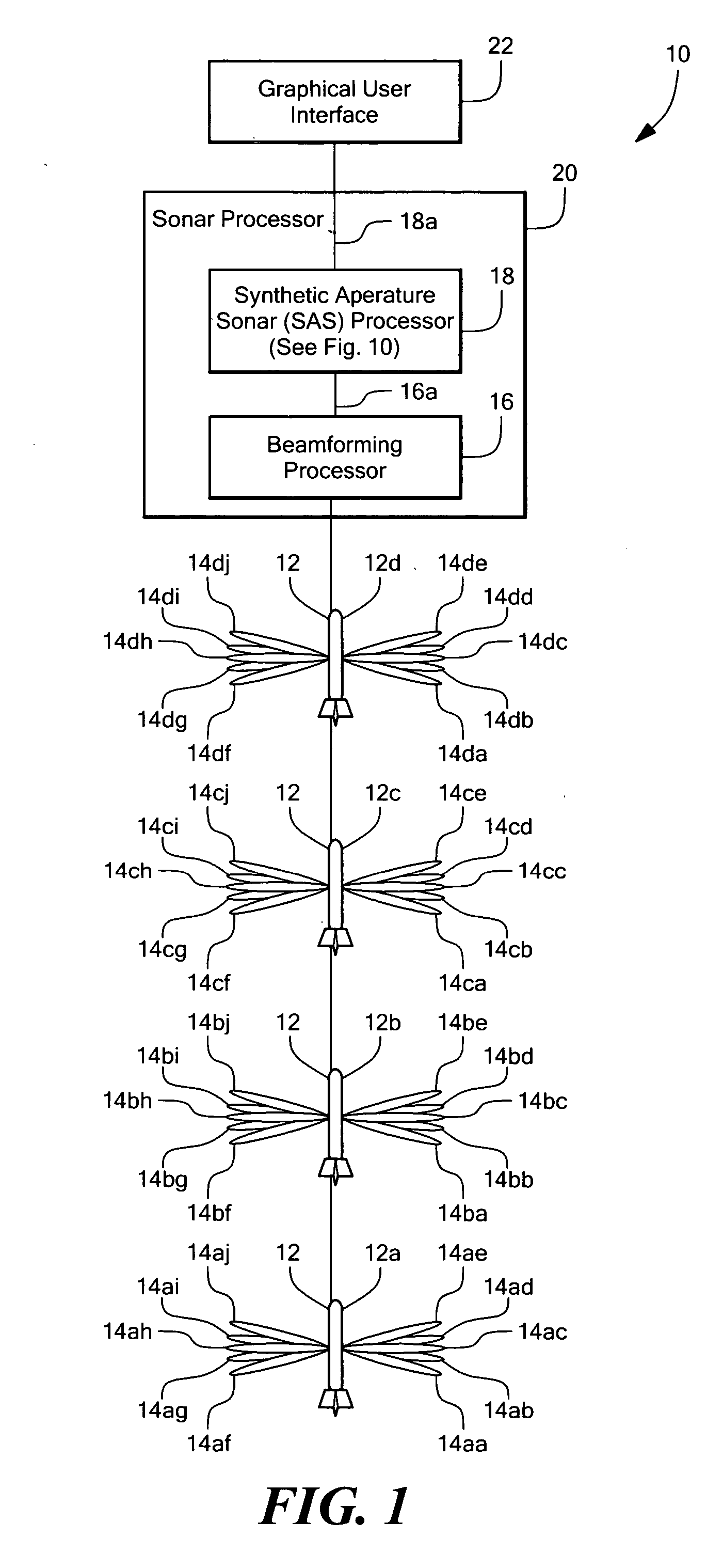
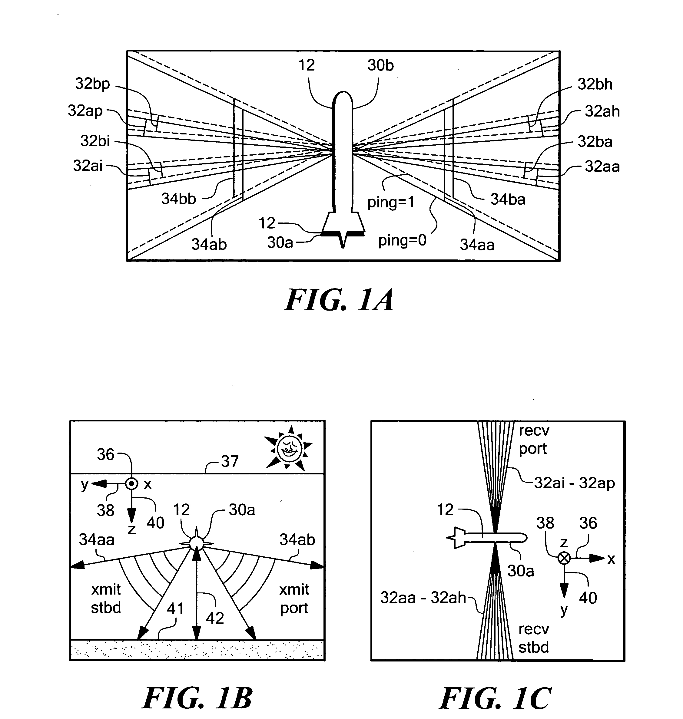
[0055] Before describing the method and system for a synthetic aperture sonar as contemplated herein, some introductory concepts and terminology are explained. As used herein, the term “side-scan sonar” refers to a type of sonar system having a tow body upon which a receive array having receive elements is disposed. The receive array of the side-scan sonar is generally horizontally disposed, and is subject to movements of the tow body. The receive array of the side-scan sonar can be used to generate “receive beams.” The tow body of the side-scan sonar can also include a transmit array to generate a “transmit beam” that can have the same beam shape or a different beam shape than the receive beams. The receive array and the transmit array can be the same physical array used in a receive mode or in a transmit mode. The side-scan sonar can operate in a monostatic arrangement.

[0056] As used herein, the term “towed array” is used to describe a receive array, which is towed through the wa...


PUM


Abstract

A method and system for synthetic aperture sonar provide improved position estimates of a receive array as in moves through a body of water.

Description

CROSS REFERENCE TO RELATED APPLICATIONS [0001] Not Applicable. STATEMENT REGARDING FEDERALLY SPONSORED RESEARCH [0002] Not Applicable. FIELD OF THE INVENTION [0003] This invention relates generally to synthetic aperture sonar and, more particularly, to a method and system for synthetic aperture sonar that provide improved spatial position of a moving sonar array used in a synthetic aperture sonar. BACKGROUND OF THE INVENTION [0004] Active sonar transmits a signal into the water, and receives echoes from targets in the water. The targets can include, but are not limited to, submarines, torpedoes, tethered mines, bottom mines, cables, and bottom features such as hills, trenches, and the bottom surface. [0005] Active sonar systems have a variety of configurations. Bistatic active sonar systems have an acoustic transmitter separate from an acoustic receiver. Monostatic active sonar systems have an acoustic transmitter co-located with an acoustic receiver. [0006] The acoustic receiver po...

Claims


Application Information

Patent Timeline
Patent Type & Authority Applications(United States)
IPC IPC(8): G01S15/00
CPCG01S7/52003G01S7/52004G01S15/8904
Inventor KOSALOS, JAMES G.KERFOOT, IAN B.
Owner RAYTHEON CO
Learn More