Dispenser with suction chamber

a dispenser and suction chamber technology, applied in the direction of liquid/fluent solid measurement, liquid transfer device, instruments, etc., can solve the problems of undesirable product string dripping out of the dispensing nozzle, undesirable mess, and compromising the integrity of the foam created in the subsequent dispensing

Active Publication Date: 2006-05-25
KANFER JOSEPH S
View PDF12 Cites 13 Cited by
  • Summary
  • Abstract
  • Description
  • Claims
  • Application Information

AI Technical Summary

Benefits of technology

[0004] The present invention provides a dispenser for dispensing a soap product. The dispenser includes a soap pump, a dispensing nozzle, and an expandable and contractible suction chamber. The dispensing nozzle has an outlet for dispensing soap, and the suction chamber is disposed between the soap pump and the dispensing nozzle. The suction chamber is expandable and contractable in volume and is predisposed to an expanded volume. Actuation of the soap pump causes the suction chamber to contract to a contracted volume that is less than the expanded volume to which it is predisposed, and soap is forced through the suction chamber and the dispensing nozzle to the outlet where it is dispensed. Soap that has not been dispensed at the outlet resides in the dispensing nozzle after actuation of the soap pump, and this residual soap is sucked back into the suction chamber during a return of the suction chamber to the expanded volume to which it is predisposed.
[0

Problems solved by technology

When the product is dispensed in this manner, a string of the product remains in the path through which the product was forced, and, particularly in certain dispenser configurations, this string of product can undesirably drip out of the dispensing nozzle.
This not only wastes product, but is also undesirably messy.
Such configurations require the use of strong biasing members (e.g., spring bias on the piston) to pull the string or portion thereof through the mesh, and foam sucked back to the location of foam creation can compromise the integrity of the foam created in a subsequent dispensing.

Method used


Image

  • Dispenser with suction chamber
  • Dispenser with suction chamber
  • Dispenser with suction chamber

Examples


Embodiment Construction

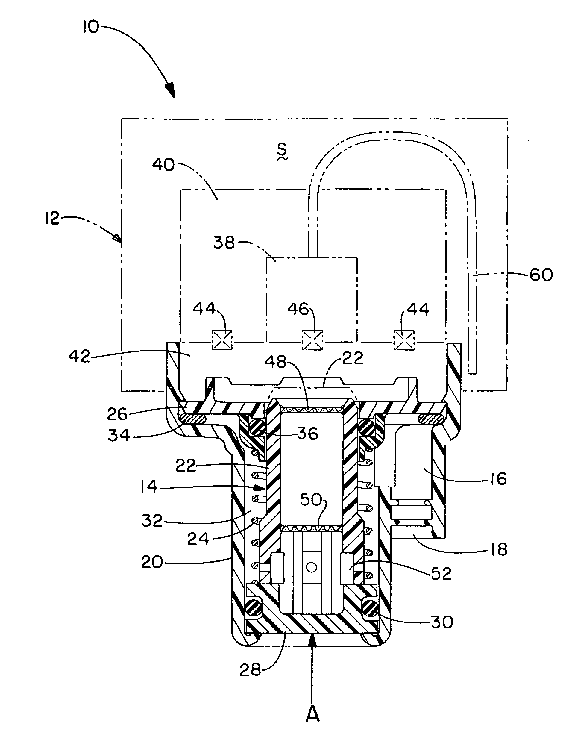
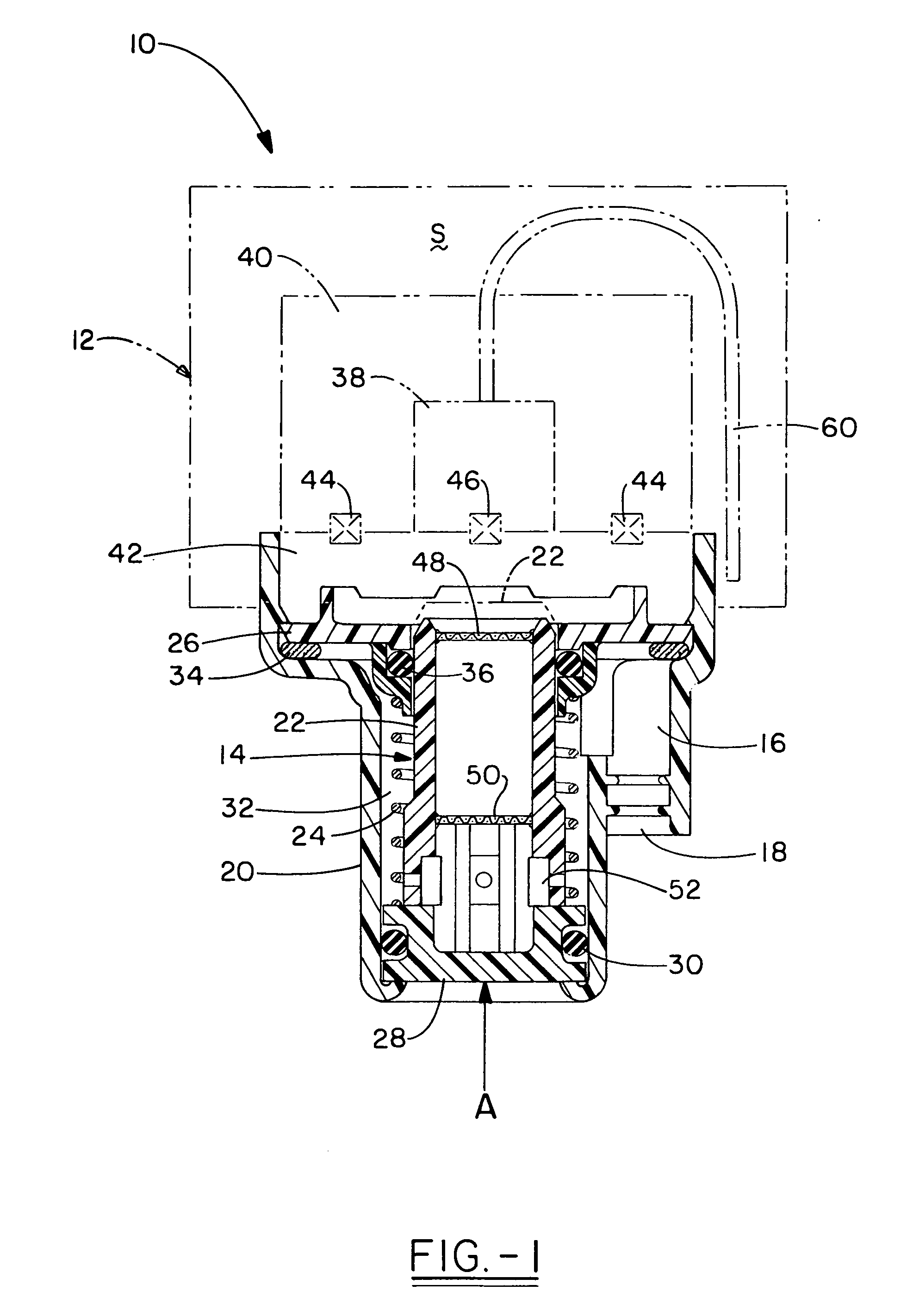
[0008] The preferred embodiment of this invention is disclosed in the environment of a foamed soap dispenser. But it should be appreciated that this invention is not limited to such an environment, and this invention will have applications in dispensers that dispense liquid soap or hand sanitizers, and may have application in other dispenser environments as well.

[0009] With reference to FIG. 1, it can be seen that a dispenser in accordance with this invention is shown and designated by the numeral 10. In dispenser 10, certain well-known elements are schematically represented, while those elements more germane to the disclosure of the present invention are represented in more detail. Dispenser 10 includes collapsible container 12, which retains liquid soap S, and foamed soap pump 14 that serves to create foamed soap from the liquid soap S in collapsible container 12 and advance that foamed soap through dispensing nozzle 16 to outlet 18. Foamed soap pump 14 is retained by an outer ho...


PUM


Abstract

A dispenser for dispensing a soap product includes a soap pump, a dispensing nozzle, and an expandable and contractible suction chamber. The dispensing nozzle has an outlet for dispensing soap, and the suction chamber is disposed between the soap pump and the dispensing nozzle. The suction chamber is expandable and contractible in volume and is predisposed to an expanded volume. Actuation of the soap pump causes the suction chamber to contract to a contracted volume that is less than the expanded volume to which it is predisposed, and soap is forced through the suction chamber and the dispensing nozzle to the outlet where it is dispensed. Soap that has not been dispensed at the outlet resides in the dispensing nozzle after actuation of the soap pump, and this residual soap is sucked back into the suction chamber during a return of the suction chamber to the expanded volume to which it is predisposed.

Description

TECHNICAL FIELD [0001] The present invention generally relates to liquid dispensers. The particular focus is on soap and hand sanitizer dispensers, although the dispenser may have applications elsewhere. More particularly, the present invention relates to a liquid dispenser having a suction chamber that serves to draw residual product back into internal elements of the dispenser to avoid dripping and other problems. BACKGROUND OF THE INVENTION [0002] The dispensers in which the present invention will find application are generally known. They consist of a reciprocating piston that is manipulated by the user to force a liquid, or in some cases foam, product through a dispensing nozzle and out an outlet thereof. When the product is dispensed in this manner, a string of the product remains in the path through which the product was forced, and, particularly in certain dispenser configurations, this string of product can undesirably drip out of the dispensing nozzle. For example, most wa...

Claims


Application Information

Patent Timeline
IPC IPC(8): G01F11/36G01F11/30G01F11/06B65D88/54G01F11/42
CPCG01F11/02
Inventor CIAVARELLA, NICK E.
Owner KANFER JOSEPH S
Why Eureka
Try Eureka