
Hair iron

a technology of hair irons and hair clips, which is applied in the field of hair irons, can solve the problems of hair damage, hair is typically subject to heat, and prior art hair irons are inefficient and undesirable, so as to reduce hair styling time, prevent hair damage, and strengthen hair

Inactive Publication Date: 2006-05-25
K I C A
View PDF18 Cites 57 Cited by
  • Summary
  • Abstract
  • Description
  • Claims
  • Application Information

AI Technical Summary

Benefits of technology

[0011] Therefore, it is an object of the present invention to provide a hair iron, which can reduce the time of hair styling, prevent hair damage and strengthen hair. Specifically, the hair iron of the present invention can facilitate hair styling by optionally supplying the hair and scalp with air, anions or steam when applying heat during hair styling.
[0012] It is another object of the present invention to provide a hair iron, which does not require a power cord to obtain the necessary power so as to be utilized without any spatial restriction while having the functions of the hair iron.
[0018] Further, it is preferred that the hair iron further comprises a means for controlling the volume of air ejected from the air-ejecting holes of the supporting member, wherein the controlling means is removably engaged with the supporting member.

Problems solved by technology

However, the above-described prior art hair irons are inefficient and undesirable for purposes of hair styling in that they lack the proper functions and structures to carry out the same.
Further, since the aforementioned prior art hair irons can style the hair only with heat, the time required for hair styling may cause the hair to be damaged.
This is because the hair is typically subjected to the heat generated from the hair iron for a prolonged amount of time.

Method used


Image

  • Hair iron
  • Hair iron
  • Hair iron

Examples


Embodiment Construction

[0060] The preferred embodiments of the present invention will now be described with reference to the accompanying drawings. Herein, the terms “front” and “rear” mean a direction going away from a hinge shaft along a hair iron and a direction facing toward the hinge shaft along the hair iron, respectively. Further, the terms “inner” and “outer” mean a direction facing toward the inside of the hair iron and a direction facing toward the outside of the hair iron, respectively.

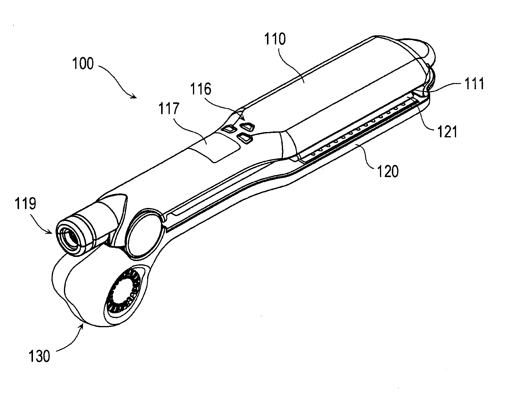
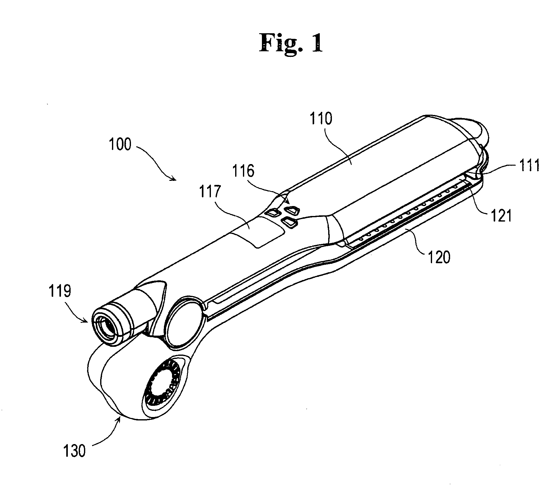
[0061]FIG. 1 is a perspective view illustrating a hair iron 100 constructed in accordance with a preferred embodiment of the present invention. FIGS. 2 and 3 are exploded perspective views of the hair iron 100.

[0062] Referring to FIGS. 1 to 3, the hair iron 100, which is constructed in accordance with a preferred embodiment of the present invention, comprises: a pair of cases 110 and 120 hinge-jointed at their respective ends and being freely opened or closed; heater plates 111 and 121 respectively mounted to t...


PUM


Abstract

The present invention relates to a hair iron adapted to reduce hair damage, strengthen hair and facilitate hair styling by blowing air toward the hair. The hair iron of the present invention is further adapted to provide hair with anions or moisture during hair styling. The hair iron includes a pair of cases hinge-jointed at each one end and being freely opened or closed, wherein each case has a heater plate for generating heat at the other end. A fan assembly for blowing air is coupled to the one end of one of the cases. An air passage through which the blown air is passed is formed inside the hair iron. An anion generator is located in the fan assembly, thereby mixing the anions with the air being transferred. Means for providing moisture is disposed adjacent to the heater plate and means for supplying the moisture-providing means with water is received in the recess formed in lower side of the case. Further, the present invention relates to a hair iron constructed without a power cord so as to be utilized without any spatial restriction while possessing all the functions of the hair iron.

Description

FIELD OF THE INVENTION [0001] The present invention generally relates to hair irons, and more particularly to a hair iron adapted to reduce hair damage, strengthen hair and facilitate hairstyling by blowing air toward the hair and providing anions or moisture during hairstyling. Further, the present invention relates to a hair iron that does not utilize a power cord, thereby being capable of being used without any spatial restriction while providing all the functions of the hair iron. BACKGROUND OF THE INVENTION [0002] Typically, hair irons are used to style hair through converting electric energy into heat energy of 60° C. to 210° C., which is then applied to the hair. Such hair irons generally include a pair of cases, which are hinge-jointed at each end, so as to be opened and closed within a certain degree of angle. Further, heater portions, which can generate heat that is applied to the hair, are provided at the inner opposing sides of the cases. [0003] Korean Utility-Model Regi...

Claims


Application Information

Patent Timeline
Patent Type & Authority Applications(United States)
IPC IPC(8): A45D1/04F24H3/02
CPCA45D1/04A45D1/06A45D20/50A45D2001/008A45D2200/202
Inventor KIM, TAI CHEULKIM
Owner K I C A
Learn More