
System and method for equipment security cable lock interface

a technology of security cable and lock interface, which is applied in the direction of unauthorized memory use protection, program control, instruments, etc., can solve the problems of equipment theft becoming a greater concern, security compromises, and limited effectiveness of theft prevention measures

Inactive Publication Date: 2006-05-18
LENOVO (SINGAPORE) PTE LTD
View PDF9 Cites 66 Cited by
  • Summary
  • Abstract
  • Description
  • Claims
  • Application Information

AI Technical Summary

Problems solved by technology

As computer equipment has become smaller and increasingly portable, the problem of equipment theft has become a greater concern.
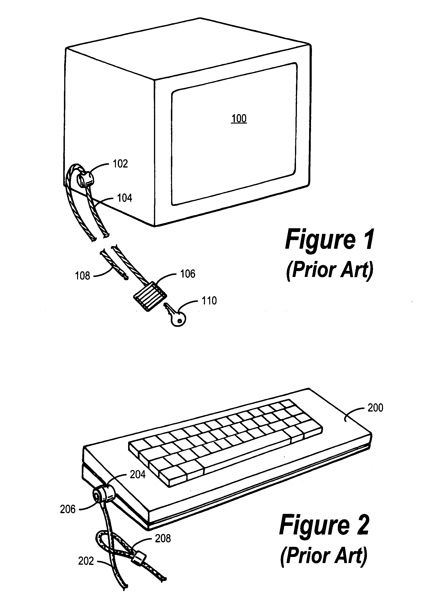
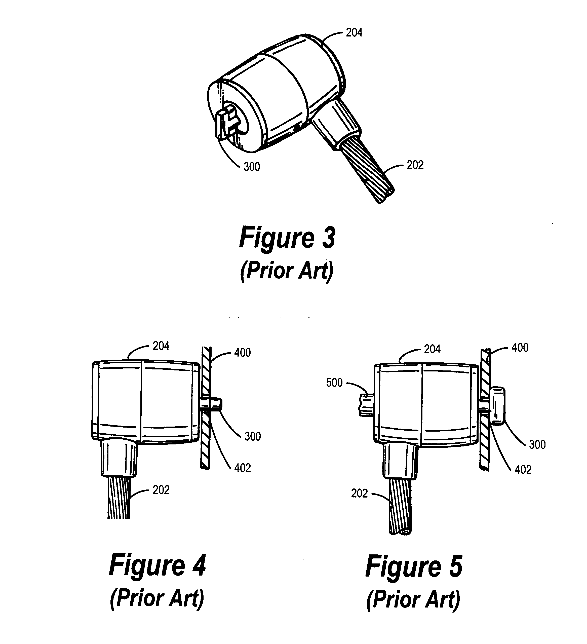
While the devices shown in FIGS. 1-5 are, from a purely physical standpoint, highly effective in preventing equipment theft, their effectiveness as a theft-preventative can be limited in practice as the result of a number of factors.
In practice, this regular reliance on a physical key tends to lead to security compromises.
Specifically, the need to use a key on a frequent basis requires that the user not lose or misplace the key, or else the cable lock cannot be unlocked and the equipment may not be removed when necessary.
This practice of leaving the key in the lock, however, essentially defeats the purpose of the cable lock in the first place, and is an unacceptable security risk.

Method used


Image

  • System and method for equipment security cable lock interface
  • System and method for equipment security cable lock interface
  • System and method for equipment security cable lock interface

Examples


Embodiment Construction

[0025] The following is intended to provide a detailed description of an example of the invention and should not be taken to be limiting of the invention itself. Rather, any number of variations may fall within the scope of the invention, which is defined in the claims following the description.

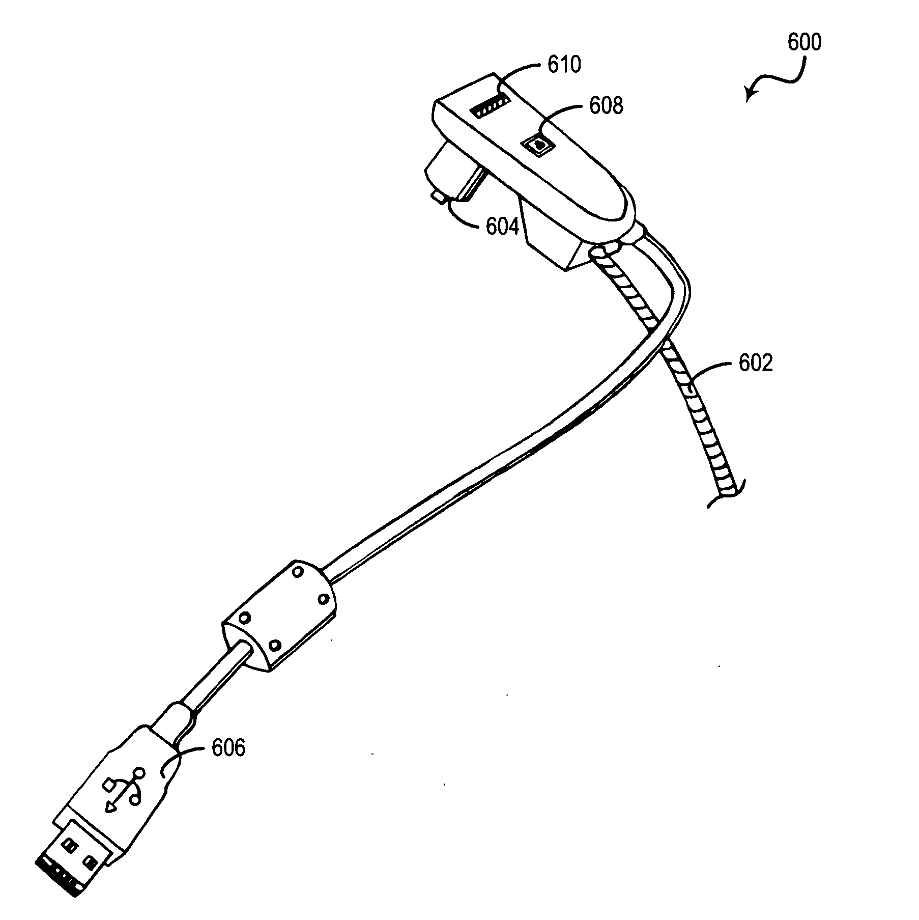
[0026]FIG. 6 is a pictorial diagram providing an external view of a cable lock device 600 in accordance with a preferred embodiment of the present invention. Cable lock device 600, like the cable lock device depicted in FIG. 2, utilizes a cable 602 that is attached to a plug 604. Plug 604 uses a similar mechanism to that depicted in FIGS. 3-5 to attach plug 604 to a hardware device, such as a mobile computer. Cable 602 is preferably affixed at one end to a stationary surface in a manner similar to the device in FIG. 2.

[0027] Cable lock device 600 has an attached USB (Universal Serial Bus) cable 606, which may be used to connect cable lock device 600 to an available USB port on a host comput...


PUM


Abstract

A cable lock apparatus that is operated by the computer equipment that the apparatus is intended to protect, rather than by a key, is disclosed. According to a preferred embodiment of the invention, the cable lock is equipped with a hot-swappable computer interface, such as a Universal Serial Bus (USB) interface, for connecting to the computer. The user of the computer unlocks the cable lock by providing a password or other form of authentication to the computer. The computer transmits this authentication information, via the USB interface, to circuitry within the cable lock device, which validates the authentication information. If the authentication information validates properly, the cable lock device circuitry activates a motor or solenoid to mechanically release the cable lock.

Description

BACKGROUND OF THE INVENTION [0001] 1. Technical Field [0002] The present invention is related generally to anti-theft devices for computer equipment. Specifically, the present invention is directed to a cable lock system that may be unlocked by a computer. [0003] 2. Description of the Related Art [0004] As computer equipment has become smaller and increasingly portable, the problem of equipment theft has become a greater concern. A number of security devices exist in the art for preventing the theft of computer equipment. One particular type of device that is frequently used is a cable lock apparatus. U.S. Patent Grant MURRAY et al. (U.S. Pat. No. 5,502,989) 1996-4-2 provides examples of typical cable lock devices as exist in the art. [0005] One common configuration for a cable lock device, as known in the art, is presented in FIG. 1. A device 100 to be protected from theft (in this case, a video display monitor) is outfitted with an aperture 102 that is adapted to allow a flexible ...

Claims


Application Information

Patent Timeline
IPC IPC(8): G06F12/14
CPCE05B73/0005E05B2073/0088G06F21/88Y10T70/5009
Inventor LANE, BRADFORD EUGENEPOLISCHAK, JOHN W.
Owner LENOVO (SINGAPORE) PTE LTD
Learn More