
Dental bur and drilling method using the same

Inactive Publication Date: 2006-05-18
FUNATO AKIYOSHI
View PDF11 Cites 8 Cited by
  • Summary
  • Abstract
  • Description
  • Claims
  • Application Information

AI Technical Summary

Benefits of technology

[0007] Accordingly, it is an object of the present invention to provide a dental bur that relatively easily modifies the angle of a hole and a drilling method for drilling the hole accurately and safely using the dental bur.
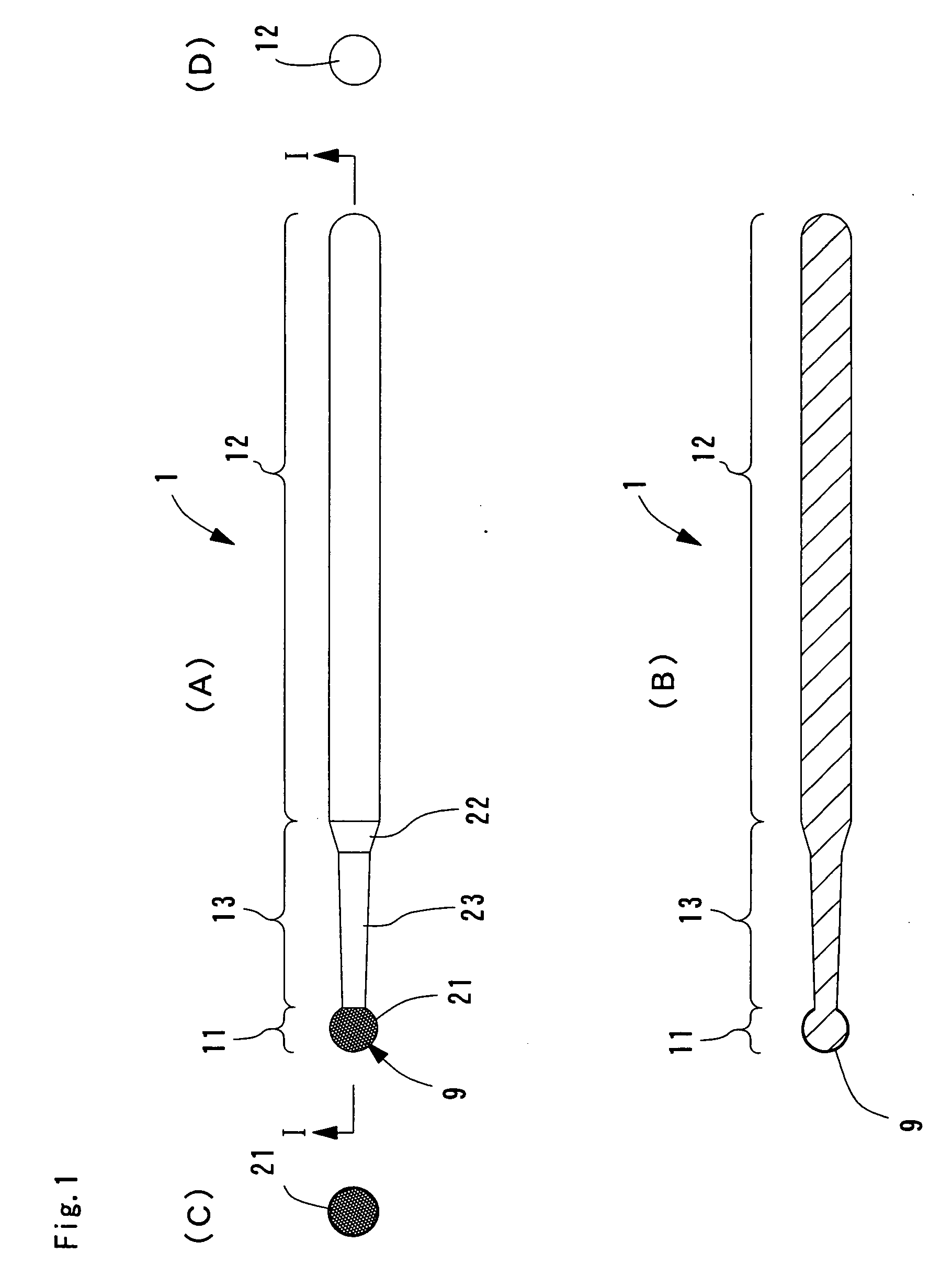
[0012] In accordance with embodiments of the present invention, the diamond particles on the cutting section having a cutting function grinds not only the bottom of the hole but also the sidewall of the hole. The angle of the hole is thus relatively easily adjusted. The neck section of the dental bur accommodates water flow, thereby preventing overheating of jawbone in the drilling operation. The neck section also serves as a depth guide of the hole.
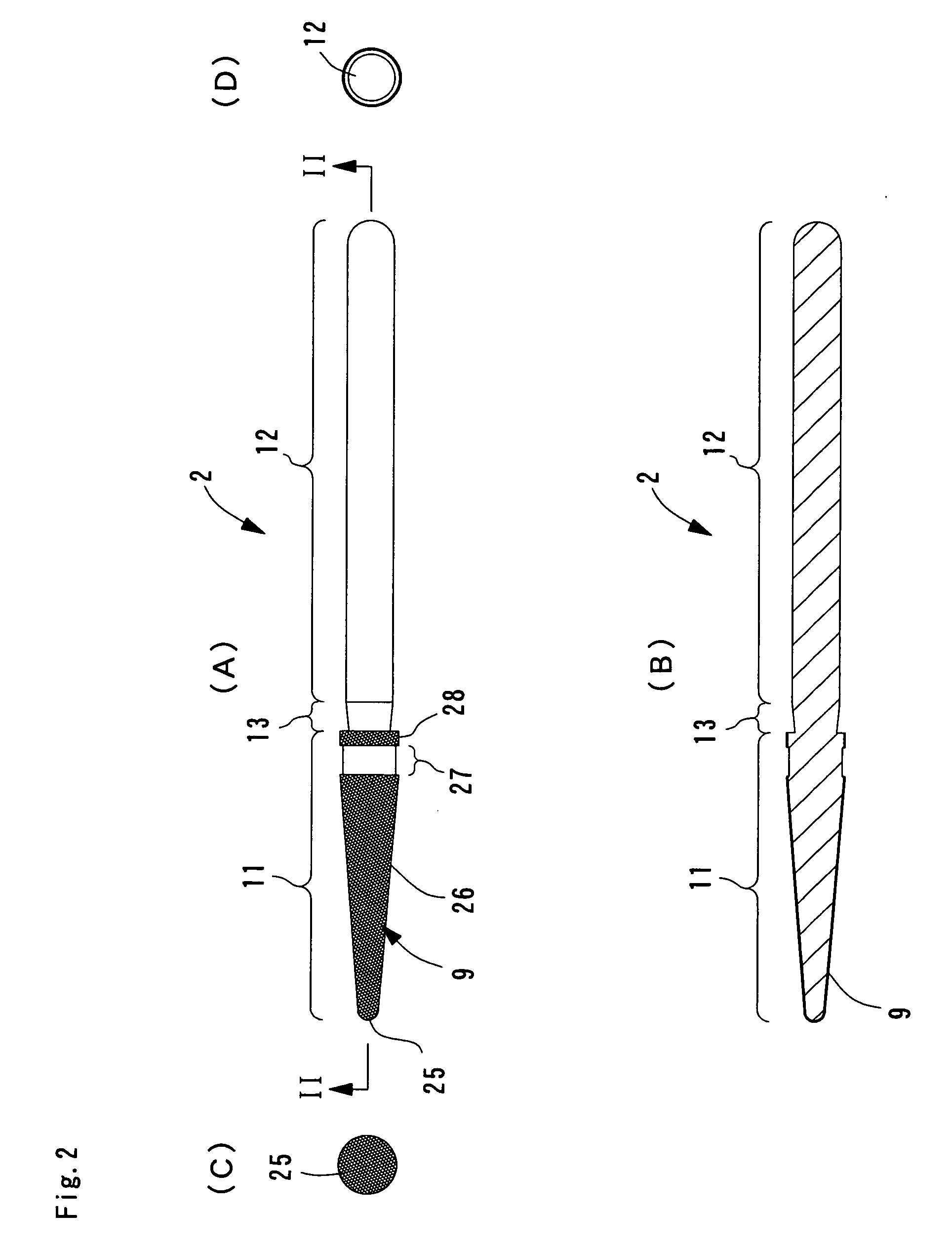
[0013] Since the cutting section has, on the surface closer to the support section, a first ring area and a second ring area alternately arranged along the longitudinal direction of the cutting section, the first ring area coated with diamond particles and the second ring area uncoated with diamond particles, the ring areas serve the depth guide of the hole. The ring area uncoated with the diamond particles forms a neck portion and holds water in the drilling operation. The overheating of the jawbone is thus further prevented.
[0014] In accordance with one embodiment of the present invention, a twist drill is used after the first through third dental burs are used. The hole is thus reliably drilled while the angle of the hole is easily modified.

Problems solved by technology

In conventional drilling methods, a hole is drilled using a twist drill from the start of a drilling operation and it is difficult to modify the angle of the hole in the middle of the drilling operation.

Method used


Image

  • Dental bur and drilling method using the same
  • Dental bur and drilling method using the same
  • Dental bur and drilling method using the same

Examples


Embodiment Construction

[0018] The embodiments of the present invention are described below with reference to the drawings.

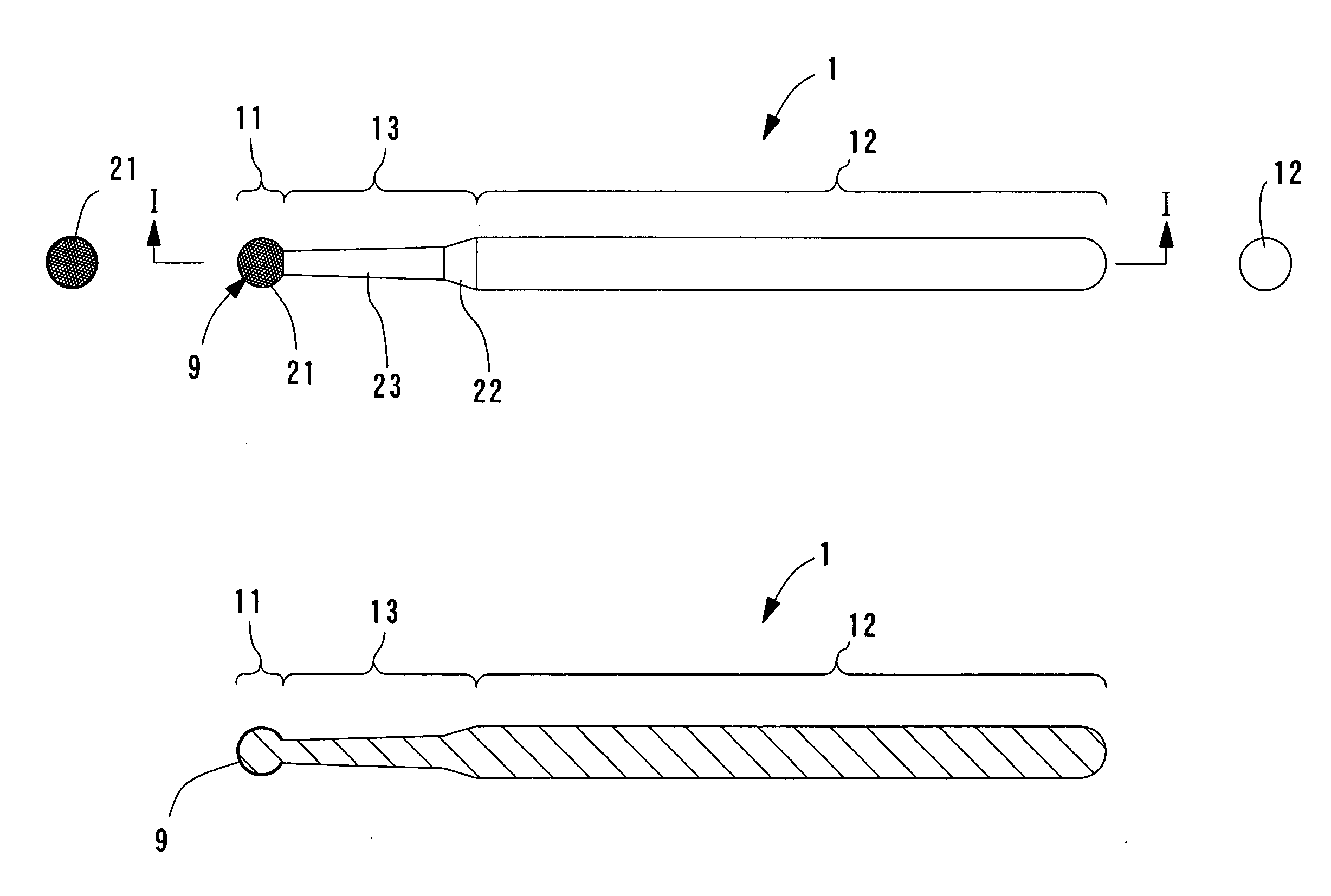
[0019]FIGS. 1A through 3D illustrate dental burs of embodiments of the present invention. In the implantation of dental practice, a variety of dental burs is used to drill holes that receive dental implants. The dental burs of FIGS. 1A through 3D illustrate examples of those dental burs. Each dental bur is a drilling instrument having a bar shape and includes, on one side thereof, a cutting section 11 for cutting jawbone and, on the other side, a support section 12 that is connected to a rotary machine.

[0020] The dental burs of FIGS. 1A through 3D are constructed of a base material such as stainless steel and the end portion of the cutting section 11 has a spherical shape. The cutting section 11 is coated with diamond particles and a neck section 13 which is formed narrow is arranged between the cutting section 11 and the support section 12.

[0021] In the drilling operation, the supp...


PUM


Abstract

A dental bur includes a cutting section on one side thereof, a support section on the other side thereof and a neck section connecting the cutting section to the support section. The cutting section has a spherical shape having a predetermined radius. The cutting section is coated with diamond particles.

Description

BACKGROUND OF THE INVENTION [0001] 1. Field of the Invention [0002] The present invention relates to a dental bur for use in dental implantation for placing implants in place of a missing tooth in dental practice. [0003] 2. Description of the Related Art [0004] Implantation is known as a restoration technique for a missing tooth in dental treatment. A hole is drilled in a tooth missing portion of the jawbone and an implant is inserted into the hole. An exposed section of the implant out of the jawbone is covered with an upper structure such as an artificial tooth. It is known that the position, depth, and angle of the implant greatly affect the function and the aesthetic quality of the super structure of the implant. [0005] In conventional drilling methods, a hole is drilled using a twist drill from the start of a drilling operation and it is difficult to modify the angle of the hole in the middle of the drilling operation. [0006] Furthermore, in the conventional drilling methods, a...

Claims


Application Information

Patent Timeline
IPC IPC(8): A61C3/02
CPCA61C3/02
Inventor FUNATO, AKIYOSHI
Owner FUNATO AKIYOSHI
Learn More