
Detector supporting mechanism

Inactive Publication Date: 2006-05-18
TOKYO SEIMITSU
View PDF11 Cites 30 Cited by
  • Summary
  • Abstract
  • Description
  • Claims
  • Application Information

AI Technical Summary

Benefits of technology

[0017] In view of the above-described circumstances, an object of the present invention is to provide a detector supporting mechanism capable of changing the detection direction of a detector in one motion with respect to various workpieces and easily making measurements on outer and inner peripheral surfaces and a flat surface of a cylinder.
[0020] According to the present invention, the second arm on which the detector is held supported so as to rotatable about the rotation axis provided on a plane inclined at an angle of 45° from the movement axis of the mount while being inclined at an angle of 45° from the movement axis of the mount in a projection on a plane which is inclined at an angle of 45° from the plane inclined at an angle of 45° from the movement axis of the mount, and which contains the movement axis of the mount. Also, the axis of the detector mounted on the second arm intersects the rotation axis. The detection direction of the detector can be changed through an angle of 90° by only turning the second arm through an angle of 120°. Therefore, the detector supporting mechanism can change the detection direction of the detector from a horizontal direction to a vertical direction in one motion.
[0022] According to the present invention, since the point of detection by the detector is at a certain distance from the movement axis of the mount, interference between a large-diameter workpiece and the mount can be avoided even in the case of measurement on an inner peripheral portion of a bore in the large-diameter workpiece.
[0026] According to the present invention, the second arm is automatically turned by the drive device to automatically change the detection direction of the detector, thus automatizing measuring operations.
[0027] As described above, the detector supporting mechanism of the present invention is capable of easily changing the detection direction of the detector from a horizontal direction to a vertical direction in one motion.

Problems solved by technology

The operation for changing the detection direction is complicated.
Therefore there is a problem that an outer peripheral portion of a large-diameter workpiece interferes with the lower end of the supporting arm 111 at the time of measurement of a bore at a center of the workpiece.
The detector supporting mechanism disclosed in Japanese Patent Application Laid Open No. 06-300505 is capable of changing the detection direction from the horizontal direction to the vertical direction in one motion, but has a problem in the case of measurement of a bore at a center of a large-diameter workpiece because of its restricted bosom, as does the detector supporting mechanism disclosed in Japanese Patent Application Laid Open No. 11-063971.
It also has a problem that when the detection direction is vertical, the lever 3 la of the detector 31 cannot be projected in a direction perpendicular to the movement axis HC of the mount 21, and the adaptable width is restricted with respect to various objects to be measured.

Method used


Image

  • Detector supporting mechanism
  • Detector supporting mechanism
  • Detector supporting mechanism

Examples


Embodiment Construction

[0045] A preferred embodiment of a detector supporting mechanism in accordance with the present invention will be described in detail with reference to the accompanying drawings. In the drawings, members identical to each other are indicated by the same numerals or characters.

[0046] The detector supporting mechanism in accordance with the present invention can be suitably used, for example, in a circularity measuring apparatus for measuring attributes of a cylindrical workpiece including the circularity and the cylindricity. The circularity measuring apparatus will first be outlined.

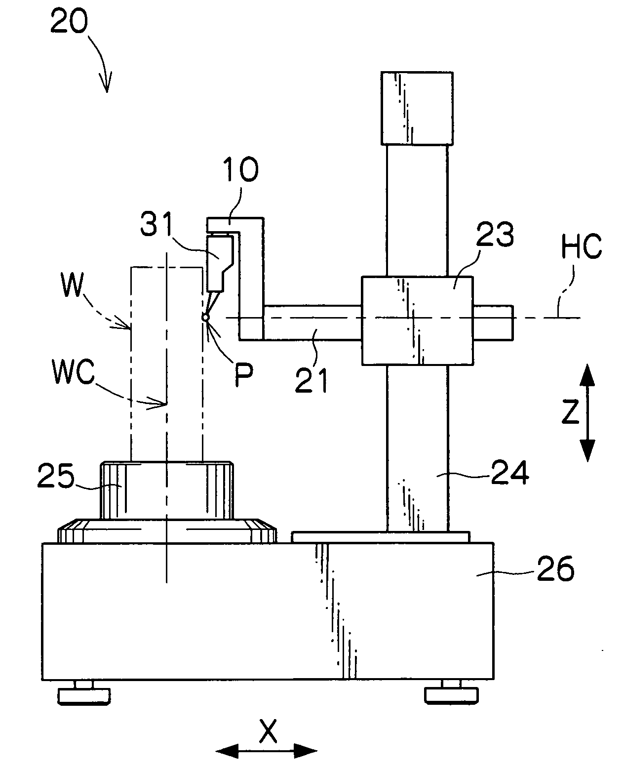
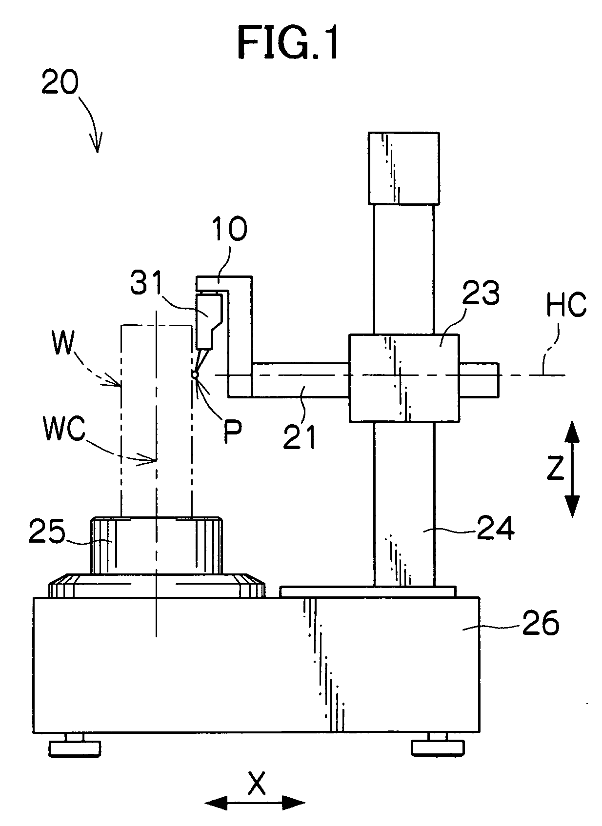
[0047]FIG. 1 is a front view of an appearance of the circularity measuring apparatus. The circularity measuring apparatus 20 has a base 26, a turntable 25 on which a workpiece W is placed and which rotates about a rotational centerline WC with accuracy, a column 24 standing upright on the base 26, a vertically movable support 23 vertically movable along the column 24 in the Z-direction shown in the fig...


PUM


Abstract

A detector supporting mechanism comprising a first arm having its one end fixed on a mount linearly movable relative to a workpiece, the first arm having a rotation axis at the other end and a second arm provided on the first arm so as to be turnable on the rotation axis relative to the first arm, a detector being mounted on a tip of the second arm, wherein the rotation axis is provided on a plane inclined at an angle of 45° from the movement axis of the mount while being inclined at an angle of 45° from the movement axis of the mount in a projection on a plane which is inclined at an angle of 45° from the plane inclined at an angle of 45° from the movement axis of the mount, and which contains the movement axis of the mount, and wherein an axis of the detector mounted on the second arm intersects the rotation axis.

Description

BACKGROUND OF THE INVENTION [0001] 1. Field of the Invention [0002] The present invention relates to a detector supporting mechanism and, more particularly, to a detector supporting mechanism for supporting a detector which is used, for example, in a circularity measuring apparatus to detect a small displacement of a workpiece. [0003] 2. Related Art [0004] A workpiece having a cylindrical shape is rotated about its axis and the circularity, the cylindricity or the like of the workpiece is measured. For example, a workpiece W shown as a workpiece with a flange in FIG. 12 is rotated about a rotational centerline WC, and the circularity of an outer peripheral portion of the cylinder is measured by bringing a probe P of a lever-type detector 31 or the like into contact with the outer peripheral portion of the cylinder and by detecting a runout of the outer peripheral portion. Alternatively, the circularity of a bore is measured by bringing the probe P of the detector 31 into contact wit...

Claims


Application Information

Patent Timeline
IPC IPC(8): G01B5/004
CPCG01B5/0002
Inventor TAKANASHI, RYO
Owner TOKYO SEIMITSU
Learn More