
Endoluminal device having enhanced affixation characteristics

a technology of endoluminal devices and affixing characteristics, which is applied in the field of endoluminal devices, can solve the problems of slow and continuous dilation of the lumen, blood flow undetected to the aneurysm, and decrease in the structural and elastic properties of the artery, and achieve the effect of inhibiting the diametric expansion of the aneurysm

Inactive Publication Date: 2006-05-11
LIFESHIELD SCI
View PDF33 Cites 72 Cited by
  • Summary
  • Abstract
  • Description
  • Claims
  • Application Information

AI Technical Summary

Benefits of technology

"The invention is about an endoluminal device that can be used to repair damaged body lumens, such as an aneurysm. The device has a neck region with a narrow width and a shoulder region with a wider width. It has a compressed configuration for easy introduction into the body lumen and a radially expanded configuration for deployment. The device has affixation members that help it stay in place on the lumen wall. The invention also includes a method for inhibiting the expansion of the aneurysm and preventing endoleak formation and migration of the endograft. The device can be a self-expanding stent or a modular device with different components that mate with each other. Overall, the invention provides an improved method for repairing damaged body lumens."

Problems solved by technology

AAA generally results from deterioration of the arterial wall, causing a decrease in the structural and elastic properties of the artery.
In addition to a loss of elasticity, this deterioration also causes a slow and continuous dilation of the lumen.
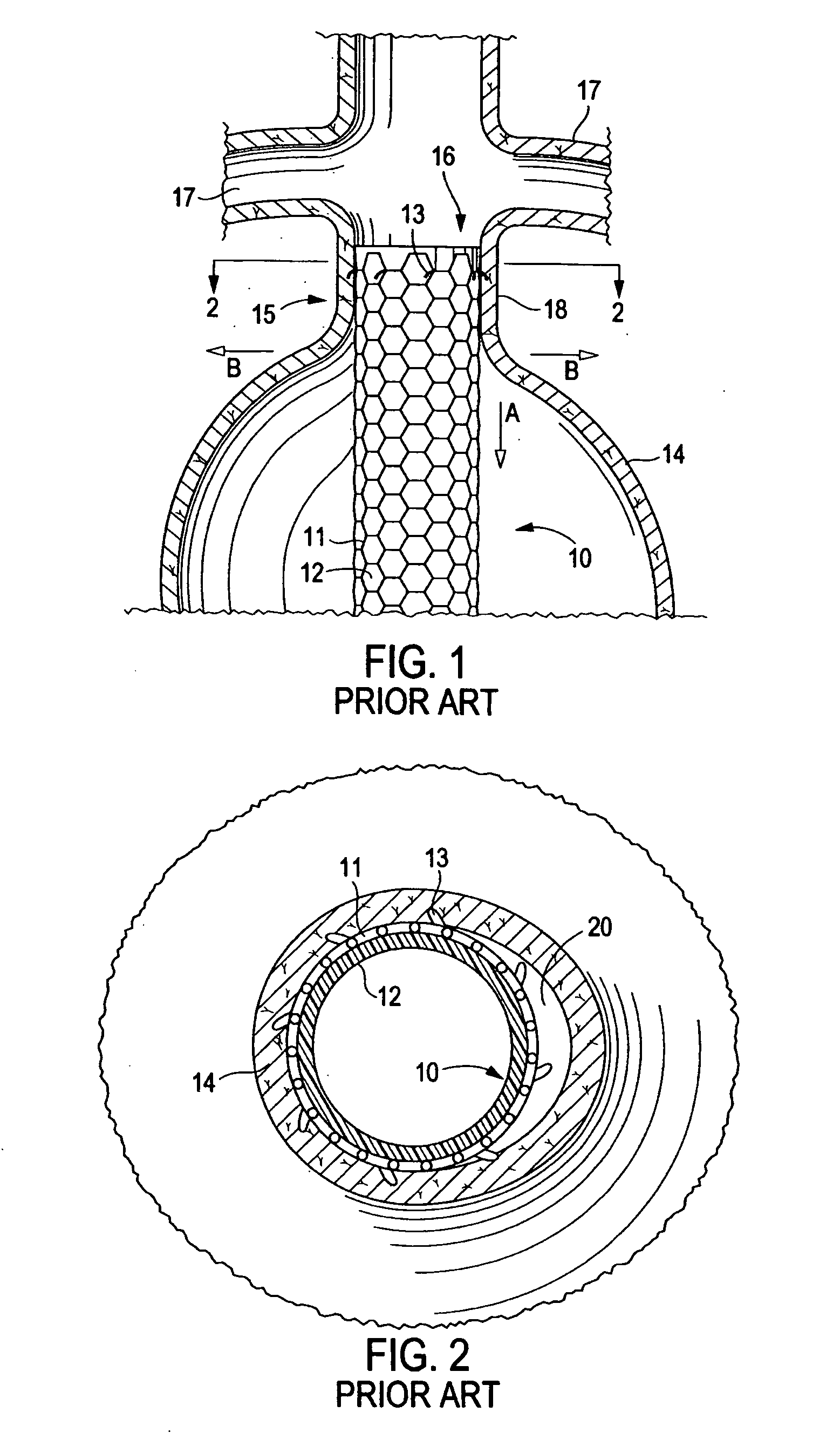
In particular, if the device migrates proximally over time in the direction of arrow A, as shown in FIG. 1, a leak at distal end 16 of the device, sometimes referred to in the art as a “Type I endoleak,” may cause blood to flow undesirably to the aneurysm.
Even with standard affixation means, however, continued progression of the aneurysm may lead to diametric expansion of the aneurysm along arrows B as shown in FIG. 1.
Accordingly, it can be seen that while the art has advanced the use of barbs to minimize migration of a deployed stent-graft, even the use of such barbs may not be sufficient to prevent endoleaks.

Method used


Image

  • Endoluminal device having enhanced affixation characteristics
  • Endoluminal device having enhanced affixation characteristics
  • Endoluminal device having enhanced affixation characteristics

Examples


Embodiment Construction

[0024] The invention will next be illustrated with reference to the figures wherein the same numbers indicate similar elements in all figures. Such figures are intended to be illustrative rather than limiting and are included herewith to facilitate the explanation of the apparatus of the present invention.

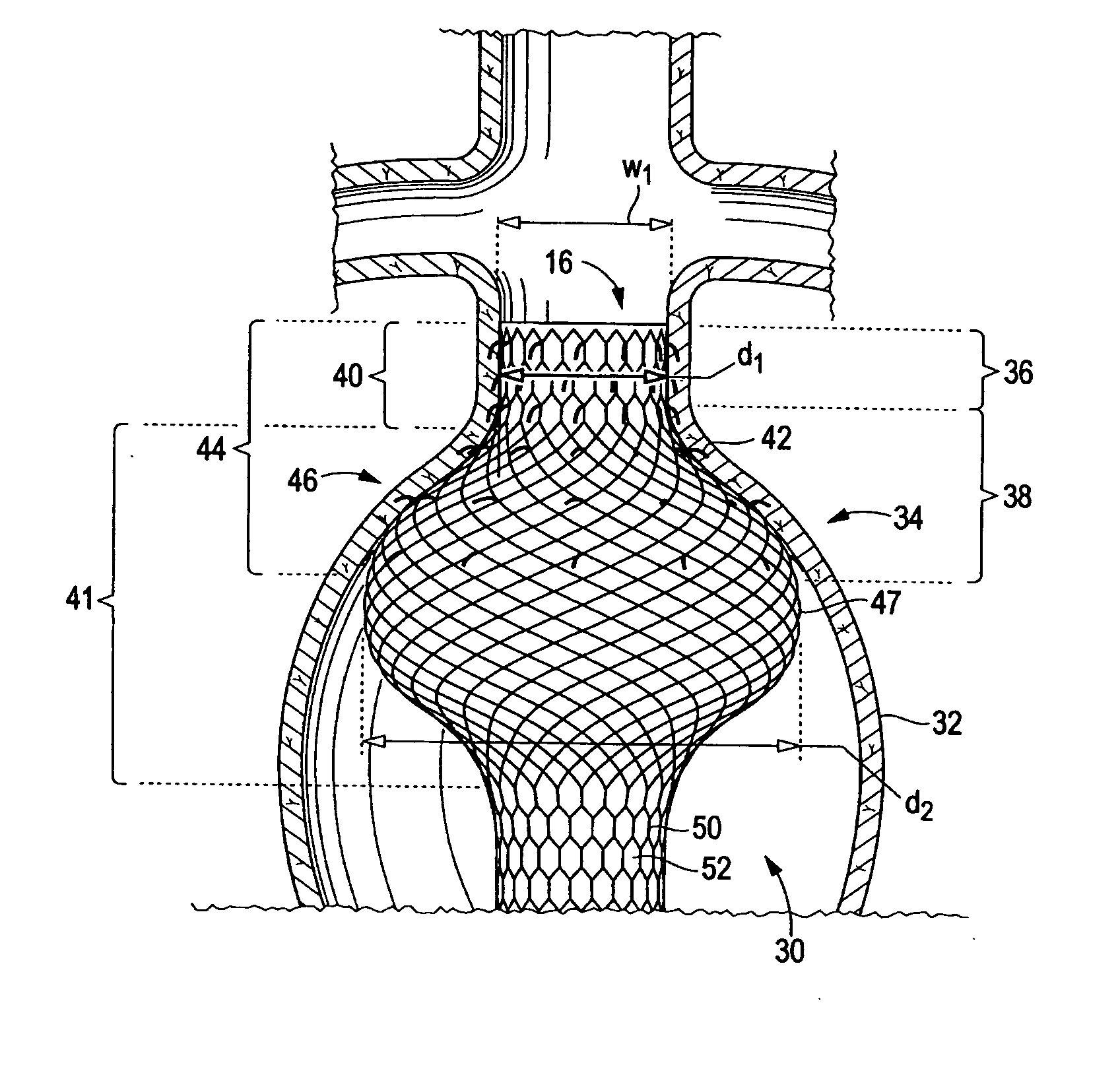
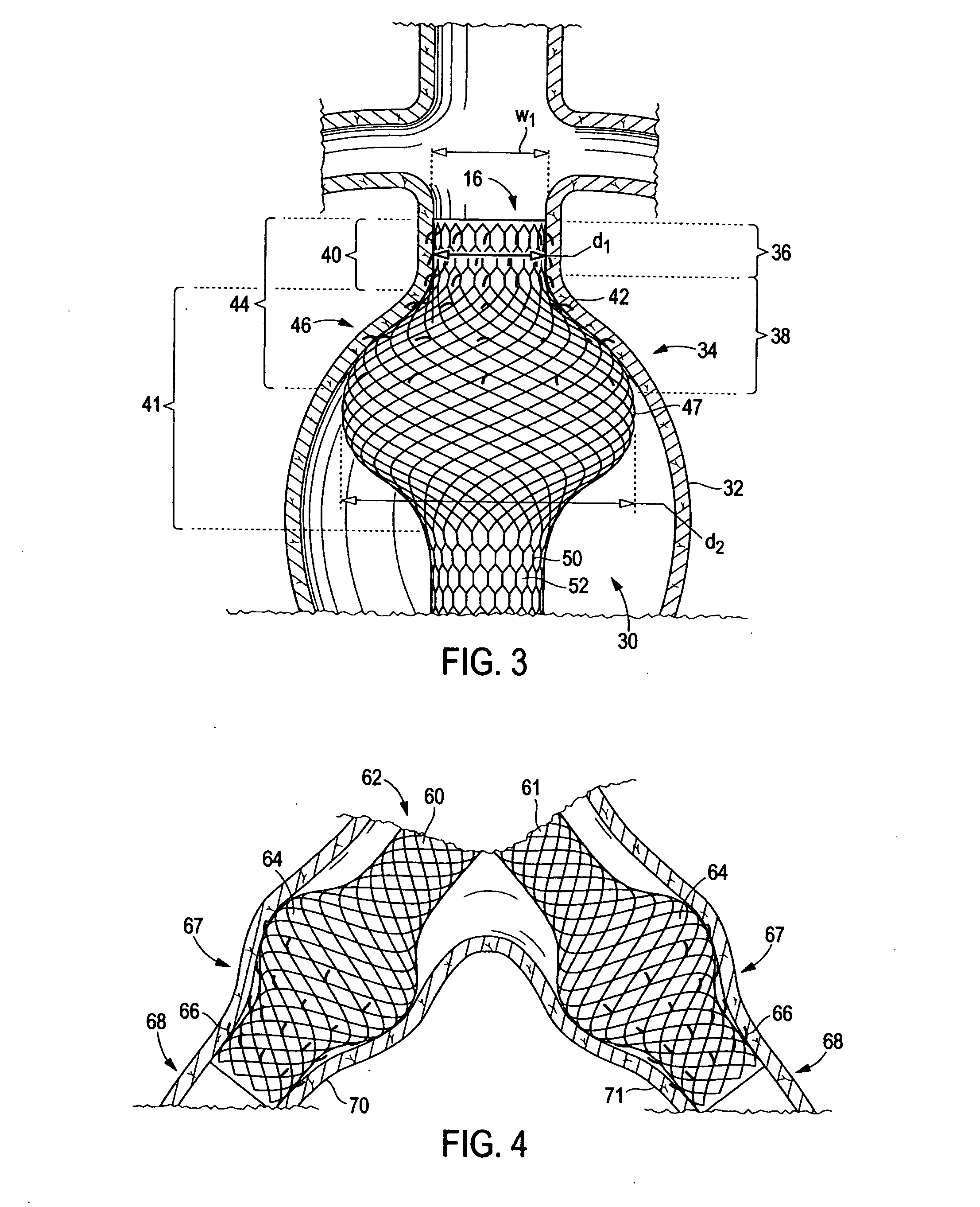
[0025] Referring now to FIG. 3, there is shown an endoluminal device 30 for affixation to the lumen wall 32 of diseased aorta 34 that is afflicted with an aneurysm. Diseased aorta 34 comprises a neck region 36 defined by a relatively narrow width w1, and a shoulder region 38 that diverges from the neck region to a relatively wider width greater than w1. Device 30 comprises a device neck 40 (also referred to herein as “distal neck” in reference to FIG. 3 and “endograft neck”) having a relatively constant diameter d1 along its length and a bulbous portion 41 having a proximally diverging then converging diameter greater than diameter d1 along its length. It should be noted that alth...


PUM


Abstract

An endoluminal device for affixation to a wall of a body lumen having a neck region defined by a relatively narrow width and a shoulder region that diverges from the neck region to a relatively wider width. The device comprises a bulbous portion having a shoulder portion with a diameter profile that conforms to the shoulder region of the lumen, and a converging diameter portion sized not to conform to the body lumen diameter profile. In some embodiments, a plurality of affixation members in an area of the device that typically extends from a distal end of the device through the shoulder portion. In one embodiment, the device comprises an endograft for repair of an aneurysm, such as an abdominal aortic aneurysm (AAA).

Description

[0001] This application is a continuation application of U.S. patent application Ser. No. 10 / 374,854, filed on Feb. 23, 2003 (status: allowed).FIELD OF THE INVENTION [0002] This invention relates generally to endoluminal devices, particularly stents and grafts for placement in an area of a body lumen that has been weakened by damage or disease, such as an aneurysm of the abdominal aorta, and more particularly to devices having characteristics that enhance affixation of the devices to the body lumen. BACKGROUND OF THE INVENTION [0003] Medical devices for placement in a human or other animal body are well known in the art. One class of medical devices comprises endoluminal devices such as stents, stent-grafts, filters, coils, occlusion baskets, valves, and the like. A stent is an elongated device used to support an intraluminal wall. In the case of a stenosis, a stent provides an unobstructed conduit through a body lumen in the area of the stenosis. Such a stent may also have a prosth...

Claims


Application Information

Patent Timeline
Patent Type & Authority Applications(United States)
IPC IPC(8): A61F2/88A61F2/00A61F2/06A61F2/90
CPCA61F2/07A61F2/848A61F2/90A61F2002/065A61F2002/077A61F2230/0076A61F2230/0054A61F2230/0071A61F2220/0016A61F2230/008A61F2220/0008A61F2250/0039
Inventor ELLIOTT, CHRISTOPHER J.
Owner LIFESHIELD SCI
Learn More