
Reflector and liquid crystal display module with the reflector

a liquid crystal display module and reflector technology, applied in the direction of mirrors, instruments, projectors, etc., can solve the problems of interference fringes or newton rings, short operation time, poor visibility, etc., and achieve the effect of preventing staining

Inactive Publication Date: 2006-05-11
NEC LCD TECH CORP
View PDF13 Cites 4 Cited by
  • Summary
  • Abstract
  • Description
  • Claims
  • Application Information

AI Technical Summary

Benefits of technology

[0015] The present invention has been proposed in view of the above-described disadvantages. The primary object of the present invention is to provide a reflector, which is capable of preventing stain caused from the interference among the beams of light due to the regularity of the projecting and recessing, and an LCD module of reflective-type or semi-transmission type provided with the reflector.
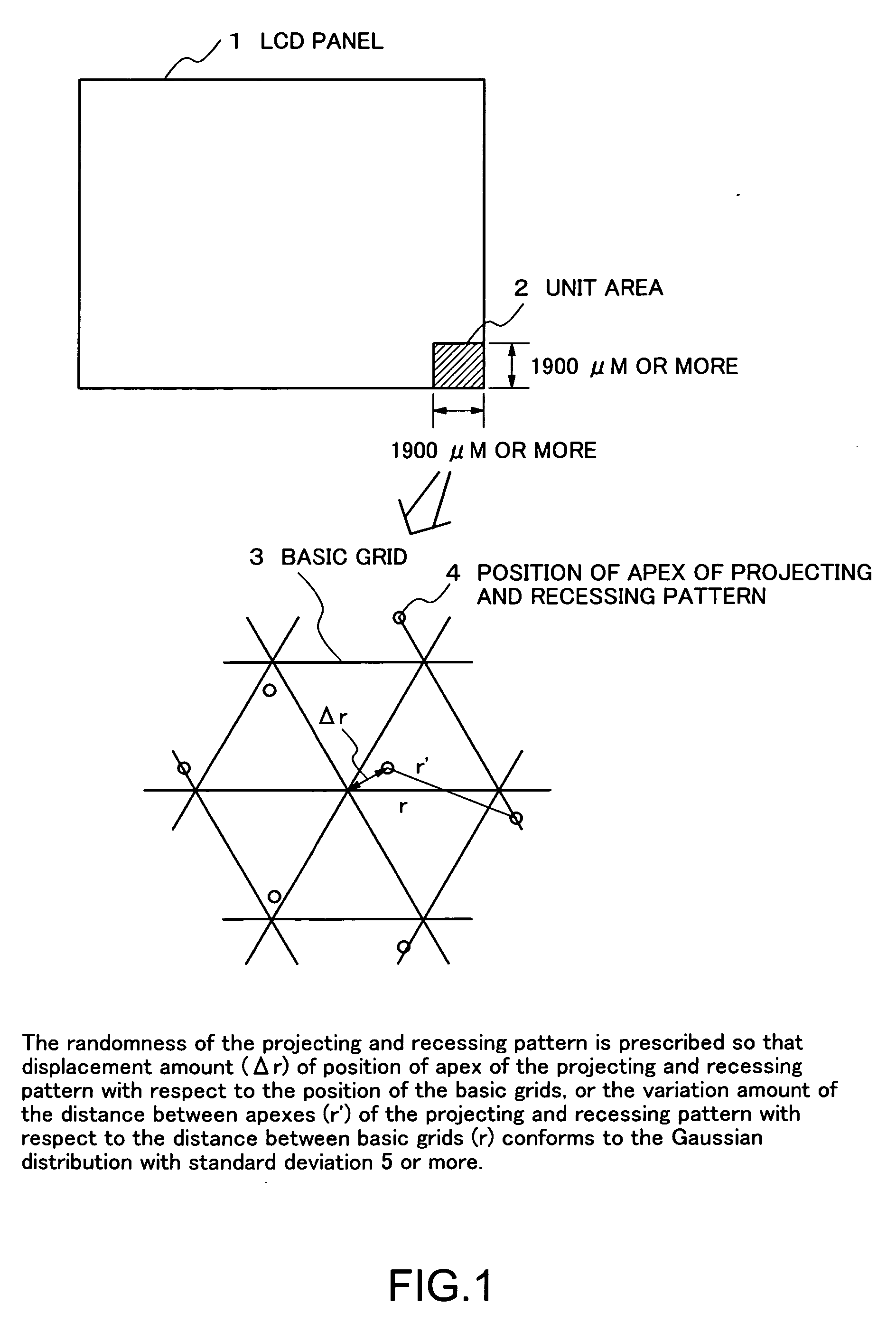
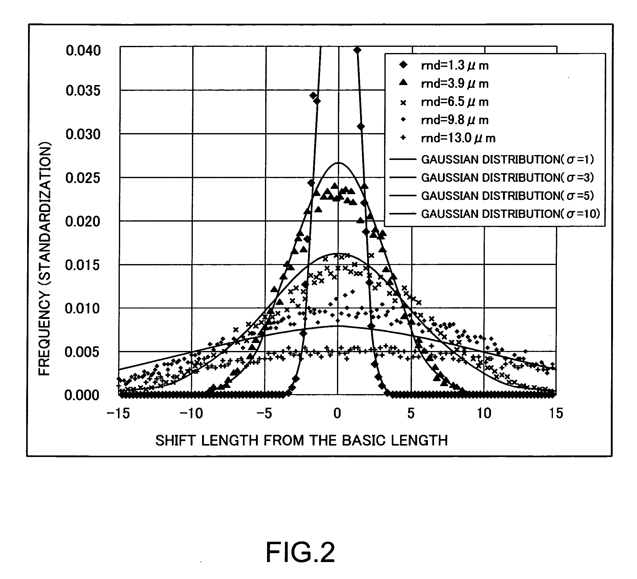
[0023] As described above, according to the arrangement of the present invention, the unit area formed with irregular projecting and recessing pattern is prescribed not by the number of dots buy by its dimension, and further, also the irregularity of the projecting and recessing pattern within each unit area is prescribed by the standard deviation of the Gaussian distribution. Accordingly, both of the interference caused from the regularity of the projecting and recessing within the unit area and the interference caused from the regularity of the projecting and recessing among the unit areas can be reliably prevented. Thus, the reflective-type LCD module or the semi-transmission type LCD module with satisfactory display quality with no stain can be achieved.

Problems solved by technology

However, the transmission-type LCD module has the following disadvantage.
That is, since the backlight source consumes a large electric power, particularly when the transmission-type LCD module is driven with a battery, the operation time is short.
However, on the other hand, there arises the following disadvantage; i.e., when the ambient is dark, sufficient reflection of ambient light used as the light source for display is hardly taken in resulting in a poor visibility.
However, in the case where the projecting and recessing of the resin layer is regularly disposed, the following disadvantage arises.
That is, particularly when beams of light, which has directivity such as direct sunlight, enters, the beams of light reflected by each projecting and recessing, interfere with each other causing interference fringes or a stain called as Newton ring.
However, the degree of the interference also varies depending on the degree of the irregularity.
Therefore, in the case where the degree of the irregularity is low, the interference cannot be prevented satisfactorily.
As a result, there resides a disadvantage such that the stain cannot be satisfactorily reduced.
However, the documents do not describe what degree the standard deviation should be different from each other.
However, the documents do not describe the degree of the irregularity.
Therefore, even when the arts disclosed in the prior art documents are applied, the stain due to the interference among the beams of light cannot be reliably prevented.
As a result, the interference of light occurs resulting in a stain.
However, since the dimensions of a pixel constituting the LCD module depends on the LCD module, even when the number of dots is prescribed, the actual dimensions of the unit area cannot be prescribed.
Therefore, the interference among the beams of light cannot be satisfactorily prevented.
Therefore, the stain cannot be prevented.

Method used


Image

  • Reflector and liquid crystal display module with the reflector
  • Reflector and liquid crystal display module with the reflector
  • Reflector and liquid crystal display module with the reflector

Examples


examples

[0056] A reflector in accordance with one embodiment of the above-described invention and an LCD module provided with the reflector will be described in detail with reference to FIG. 6 through FIG. 11.

[0057]FIG. 6 is a sectional view schematically showing the arrangement of a reflective-type LCD module in accordance with one embodiment of the present invention; and FIGS. 7A, 7B, 7C and 7D are sectional views illustrating the manufacturing process in accordance with the manufacturing method thereof. FIG. 8 is a sectional view schematically showing the arrangement of a semi-transmission type LCD module in accordance with one embodiment of the present invention; and FIGS. 9 A, 9B, 9C and 9D show sectional views illustrating the manufacturing process in accordance with the manufacturing method thereof. FIGS. 10A, 10B and 10C show observation results of an image diffracted on the reflective-type LCD module; and FIGS. 11 A, 11B and 11C show observation result of an image diffracted on a ...


PUM


Abstract

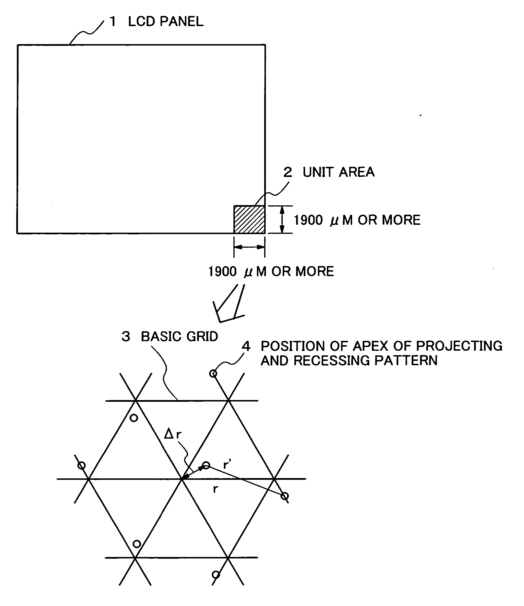
A reflector capable of preventing stain caused from the interference among the beams of light, for reflecting light incident on an LCD module to utilize the light as a light source for display. The reflector includes a plurality of projecting and recessing patterns which are irregularly disposed on the reflector, and each projecting and recessing pattern is disposed corresponding to prescribed polygon shape as a grid, and is repeated in the plane direction of the reflector so that the length of the edge or the distribution of distance between the centers of each projecting and recessing pattern conforms to the Gaussian distribution. The reflector also includes a unit area constituted of the plurality of polygon shapes, so that one edge of the unit area is integral multiple of a unit pixel and substantially 1900 μm or more, and smaller than or equal to the entire screen of the LCD module.

Description

BACKGROUND OF THE INVENTION [0001] 1. Field of the Invention [0002] The present invention relates to a liquid crystal display (LCD) module, particularly to a reflector formed on a reflective-type or semi-transmission type LCD module. [0003] 2. Description of the Related Art [0004] Since liquid crystal display (LCD) modules have features such as small in size, small thickness and low power consumption, they have been put into practical use in various fields such as office automation equipment, portable equipment. Different from CRT or EL display, an LCD has no function to emit light for oneself. Therefore, the LCD called as transmission-type is provided with a backlight source and is adapted so as to control the display by switching the transmission / shut-off of the backlight using a liquid crystal panel. The transmission-type LCD module can provide bright screen with its backlight being independent of ambient conditions. However, the transmission-type LCD module has the following dis...

Claims


Application Information

Patent Timeline
IPC IPC(8): G03B21/28
CPCG02B5/08G02F1/133553G02F2203/03
Inventor NAKA, KENICHIROUSAKAMOTO, MICHIAKI
Owner NEC LCD TECH CORP
Learn More