
Gear lever having a light emitting effect

a technology of light-emitting effect and gear lever, which is applied in the direction of gearing elements, mechanical control devices, instruments, etc., can solve the problems of user not being able to replace the circuit board, etc., to facilitate the user replacing the circuit board, and enhance the outstanding appearance of the gear lever

Inactive Publication Date: 2006-05-11
LIU YAO HUANG
View PDF11 Cites 13 Cited by
  • Summary
  • Abstract
  • Description
  • Claims
  • Application Information

AI Technical Summary

Benefits of technology

[0011] The primary objective of the present invention is to provide a gear lever having a light emitting effect.
[0012] Another objective of the present invention is to provide a gear lever, wherein the light rays emitted from the light emitting member are gathered in the light-gathering member and are emitted outward from the transparent flange of the light-gathering member and the through holes of the top cover, thereby enhancing the outstanding appearance of the gear lever.
[0013] A further objective of the present invention is to provide a gear lever, wherein the electric power of the light emitting member is supplied by the batteries of the circuit board, and the circuit board needs not to be connected to the wires contained in the car, so that a user can mount and detach the circuit board easily and conveniently, thereby facilitating the user replacing the circuit board when the circuit board is worn out during a long-term utilization.
[0014] A further objective of the present invention is to provide a gear lever, wherein the gear lever only needs to provide a single light emitting member to emit light rays through the transparent flange of the light-gathering member and the through holes of the top cover so as to enhance the outstanding appearance of the gear lever, thereby decreasing costs of the gear lever.

Problems solved by technology

However, the electric wire 111 of the circuit board 11 is connected to the wire contained in the car, so that a user cannot replace the circuit board 11 easily and conveniently when the circuit board 1 is worn out during a long-term utilization.
However, the electric wire 211 of the circuit board 21 is connected to the wire contained in the car, so that a user cannot replace the circuit board 21 easily and conveniently when the circuit board 21 is worn out during a long-term utilization.

Method used


Image

  • Gear lever having a light emitting effect
  • Gear lever having a light emitting effect
  • Gear lever having a light emitting effect

Examples


Embodiment Construction

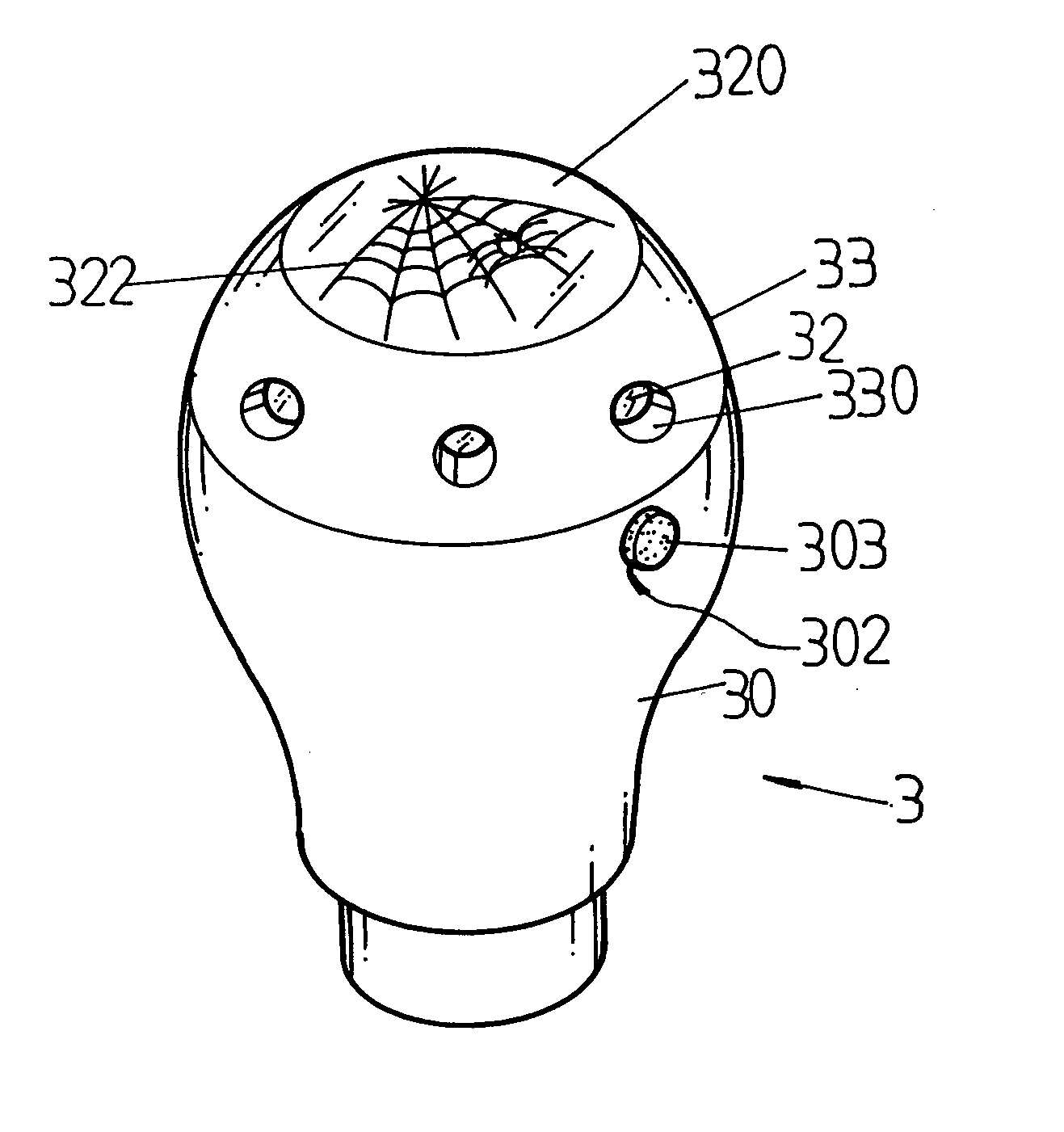
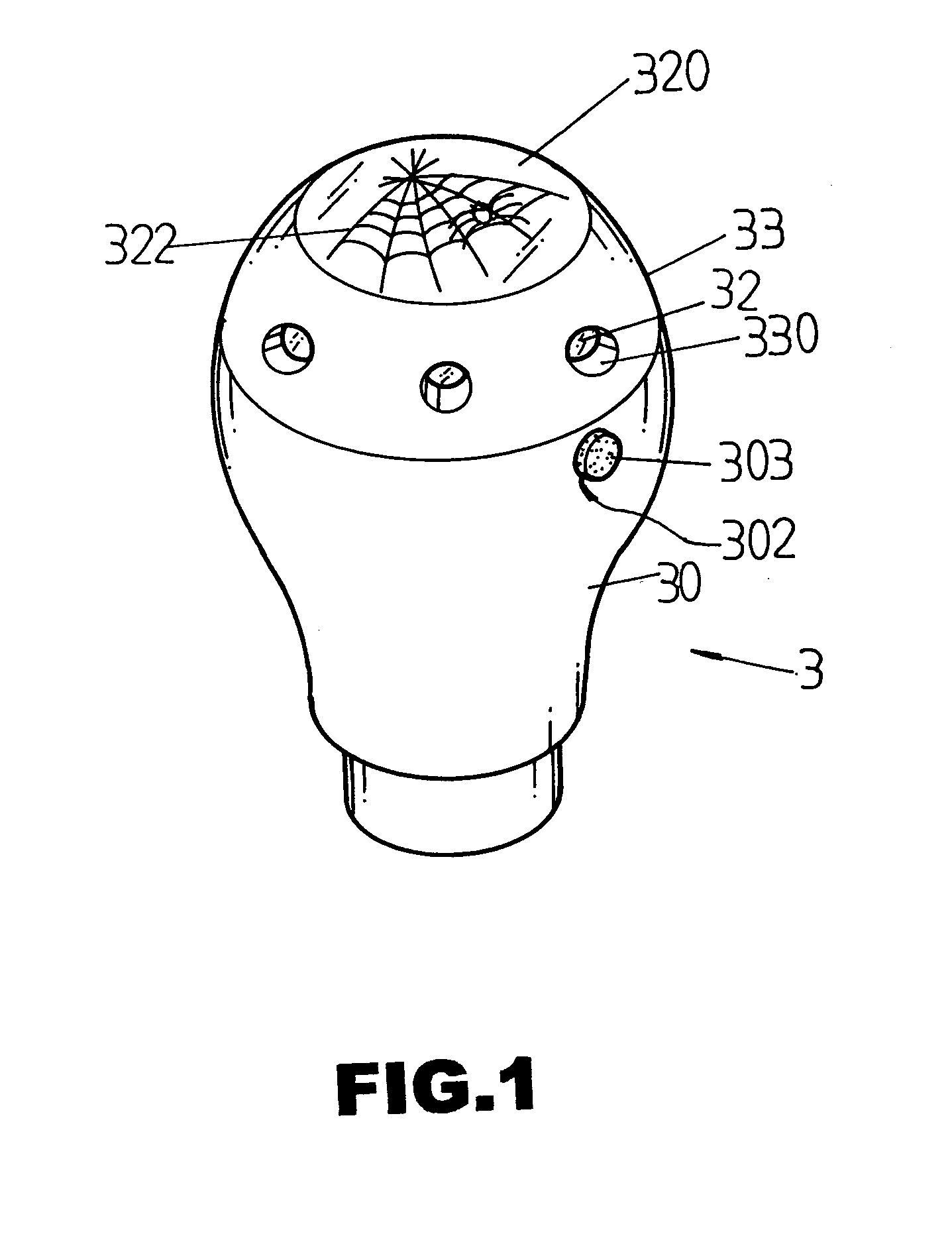
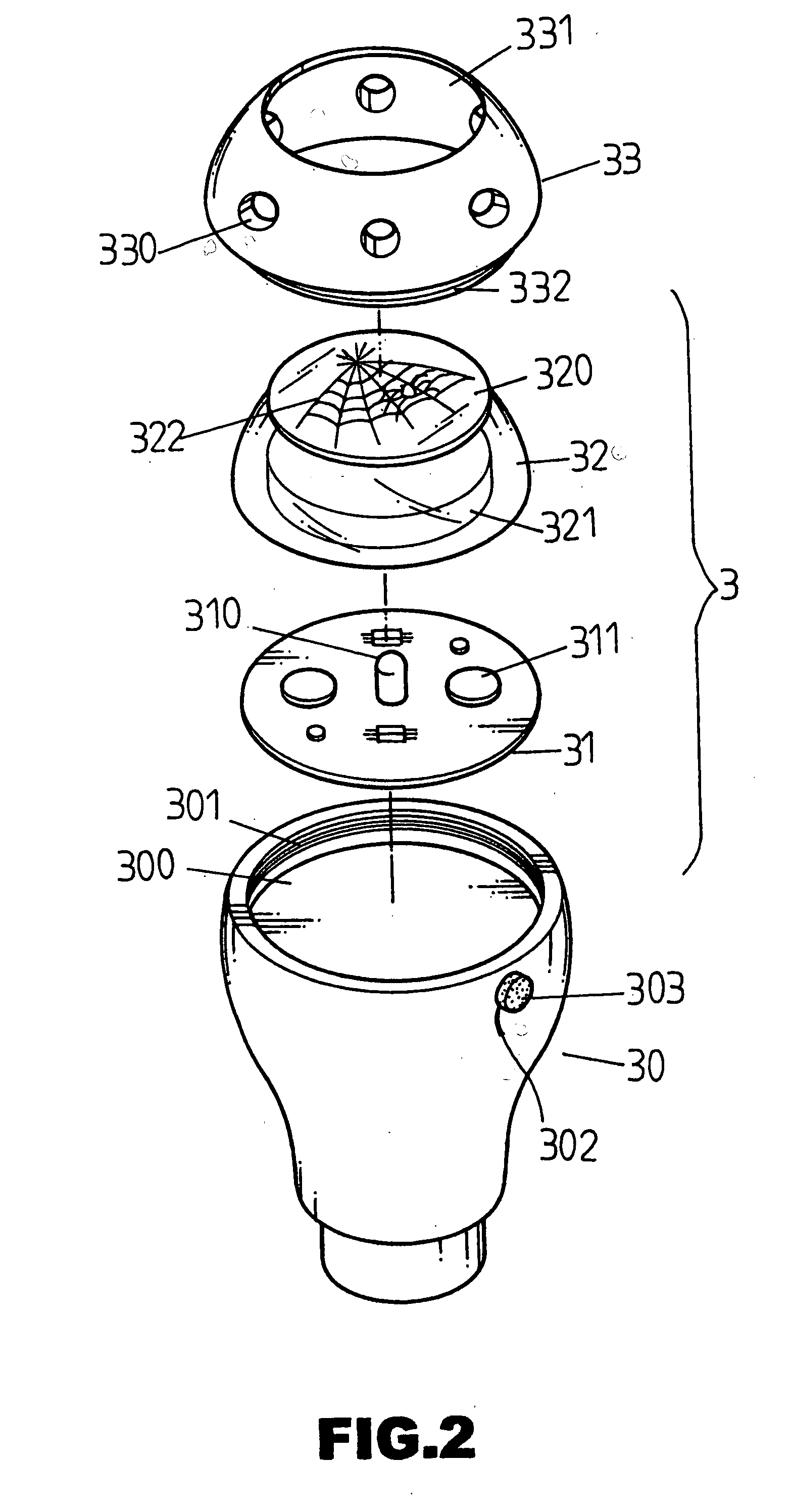
[0023] Referring to the drawings and initially to FIGS. 1 and 2, a gear lever 3 for a car in accordance with the preferred embodiment of the present invention comprises a main body 30, a top cover 33 mounted on the main body 30, a light-gathering member 32 mounted between the main body 30 and the top cover 33, and a circuit board 31 mounted between the main body 30 and the light-gathering member 32 and provided with a light emitting member 310 directed toward the light-gathering member 32.

[0024] As shown in FIGS. 1-3, the main body 30 has an upper end formed with a recess 300 to receive the circuit board 31 and formed with an inner thread 301. The upper end of the main body 30 has a peripheral wall formed with a mounting hole 302 communicating with the recess 300.

[0025] A push button 303 is movably mounted in the mounting hole 302 of the main body 30 to detachably contact with the circuit board 31 to control operation of the light emitting member 310 of the circuit board 31.

[0026...


PUM


Abstract

A gear lever for a car gear lever includes a main body, a top cover mounted on the main body, a light-gathering member mounted between the main body and the top cover, and a circuit board mounted between the main body and the light-gathering member and provided with a light emitting member directed toward the light-gathering member. Thus, the light rays emitted from the light emitting member are gathered in the light-gathering member and are emitted outward from the transparent flange of the light-gathering member and the through holes of the top cover, thereby enhancing the outstanding appearance of the gear lever.

Description

BACKGROUND OF THE INVENTION [0001] 1. Field of the Invention [0002] The present invention relates to a gear lever for a car, and more particularly to a gear lever having a light emitting effect. [0003] 2. Description of the Related Art [0004] A conventional gear lever 1 for a car in accordance with the prior art shown in FIGS. 4 and 5 comprises a main body 10 having an upper end formed with a recess 100 and an inner thread 101, a top cover 12 mounted on the main body 10 and having a lower end formed with an outer thread 121 screwed into the inner thread 101 of the main body 10 and an upper end formed with a transparent face 120, and a circuit board 11 mounted between the main body 10 and the top cover 12 and having a first side provided with a light emitting member 110 and a second side provided with an electric wire 111 connected to a wire contained in the car. When an electric power of the car is supplied to the electric wire 111, the light emitting member 110 lights and the light...

Claims


Application Information

Patent Timeline
Patent Type & Authority Applications(United States)
IPC IPC(8): G05G1/10
CPCY10T74/20732F16H59/0278
Inventor LIU, YAO-HUANG
Owner LIU YAO HUANG
Learn More