
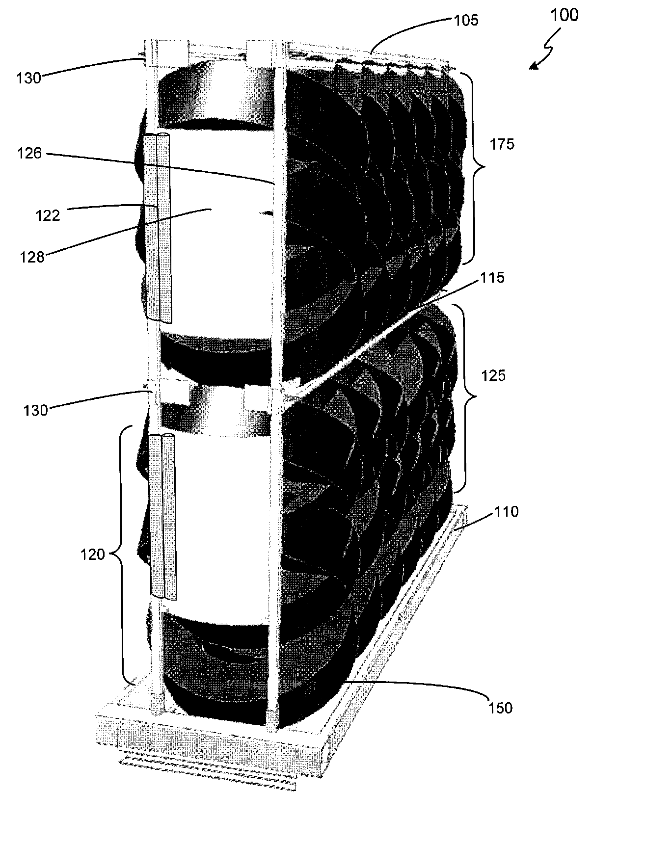
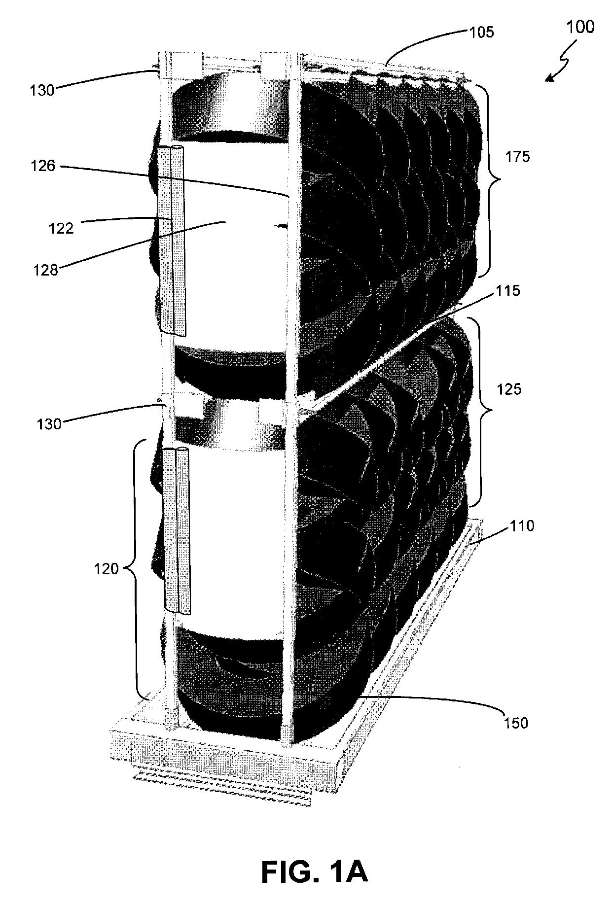
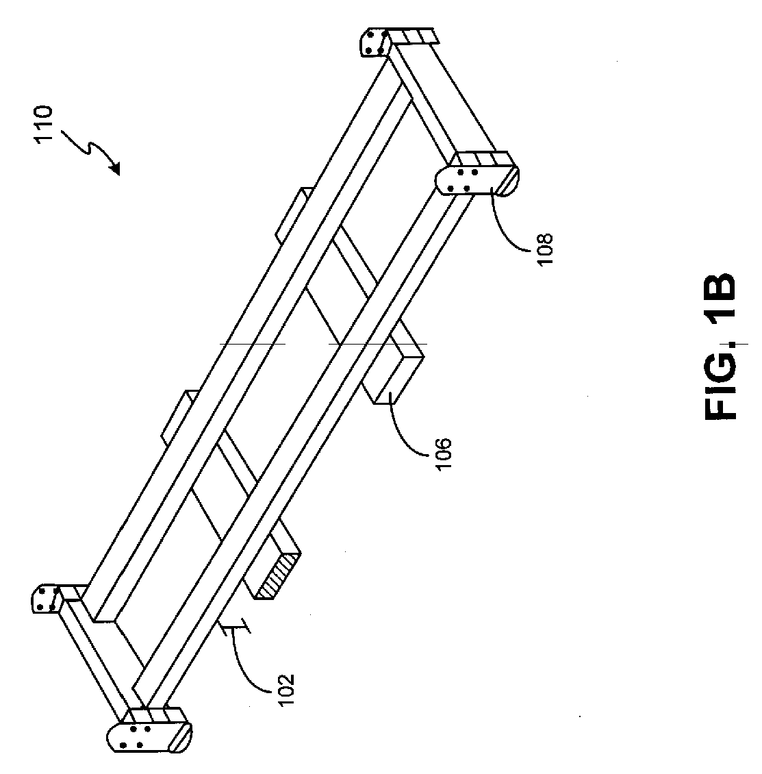
Tire rack, loading and unloading systems and methods

Inactive Publication Date: 2006-04-27
LINWELL
View PDF57 Cites 35 Cited by
  • Summary
  • Abstract
  • Description
  • Claims
  • Application Information

AI Technical Summary

Benefits of technology

[0011] The invention discloses methods and systems for sorting and unloading tires as well. For example, the systems for sorting and unloading tires of the present invention include one or more automated conveyors, scanners, and storage structures. For example, in the sorting system, the scanner can read information off of incoming t

Problems solved by technology

Further, these vessels often provide storage of tires prior to and after transport.
However, compression may lead to permanent deformation of tires in some stacking configurations.
The ricking service is a substantial labor expense at both the plant and the distribution center, while using a forklift to compress tires often results in inconsistent compression and tire damage.
These systems, however, continue to rely heavily upon manual labor to accomplish the stacking of tires.
As a result, the load exerts a downward pressure on the stack of tires, thereby compressing the tires.
However, no assurance exists that the vessel was designed or is suitable to maintain such loads.
In fact, vessels are frequently damaged as a result of such use.
However, a device does not exist that sufficiently eliminates the difficulties of manually stacking tires in a storage and / or transportation vessel, and unloading the compressed tires from the same vessel.
Moreover, no sufficient device currently exists to eliminate the reliance on the vessel to maintain a compressive load on tires.
Although loaders for tires exist, for example, a machine loader and a loader to create a straight stack of tires, the existing loaders are not designed to stack tires in a herringbone pattern.
As a result, the weight of the stacks is unevenly distributed causing further compression and strain on tires.

Method used


Image

  • Tire rack, loading and unloading systems and methods
  • Tire rack, loading and unloading systems and methods
  • Tire rack, loading and unloading systems and methods

Examples


Embodiment Construction

[0024] It should be appreciated that the particular implementations shown and described herein are illustrative of the invention and its best mode and are not intended to otherwise limit the scope of the present invention in any way. Indeed, for the sake of brevity, trivial and conventional features and aspects of the present invention are not described in extensive detail herein. Furthermore, the connecting lines shown in the various figures shown herein are intended to represent exemplary functional relationships and / or physical couplings between the various elements of the system. It should be noted that many alternative or additional functional relationships or physical connections can be present in a practical tire loading system.

[0025] The present invention includes improvements to a rack for transporting tires, improvements to an automatic tire loading system, an automatic tire unloading system, a tire sorting and short-term storage system, improvements to a tire warehousing...


PUM


Abstract

A tire loading apparatus and method of packing tires that includes placing the tires in a rack, compressing the tires, and assembling the rack are disclosed. The apparatus includes one or more conveyors, scanners, and robots that load tires from a conveyor to a rack. A tire unloading apparatus is also disclosed. The unloading apparatus includes a scissor mechanism to raise and / or lower tire racks to an unloading platform. The unloading apparatus additionally includes one or more unloaders and conveyors. The sorting and unloading of tires is accomplished with one or more automated conveyors, scanners, and storage structures for reading information from incoming tires and using the tire information to sort and store the tires. A rack to improve compression and support of tires during storage and shipment is also disclosed.

Description

CROSS-REFERENCE TO RELATED APPLICATIONS [0001] This application claims priority to, and the benefit of, U.S. Provisional Patent Application No. 60 / 600,716 entitled “IMPROVED TIRE LOADING SYSTEM AND METHOD” filed Aug. 11, 2004, and U.S. Provisional Patent Application No. 60 / 633,216 entitled “IMPROVED TIRE RACK, UNLOADING SYSTEM, SORTING SYSTEM AND METHODS” filed Dec. 3, 2004, both of which are incorporated herein by reference in their entirety.FIELD OF INVENTION [0002] The present invention generally relates to loading and unloading of tires, and more particularly, to a system and method for automatically loading and unloading vehicle tires and compressing vehicle tires for storage and / or transportation within a tire transport frame using a rack system. BACKGROUND OF INVENTION [0003] The tire distribution process often includes transporting large quantities of tires from the plants where they are manufactured to the various facilities where tires are delivered to consumers and / or mou...

Claims


Application Information

Patent Timeline
IPC IPC(8): A47F7/00
CPCB29D30/0016B29D2030/0027B65B25/24B65G1/14B65G1/16B65G2201/0273
Inventor LEIMBACH, WENDELL B.MARSHAL, JAMES WHEELERWALLACE, RICK
Owner LINWELL
Learn More