
Patient circuit disconnect system for a ventilator and method of detecting patient circuit disconnect

a patient circuit and ventilation system technology, applied in audible signalling systems, operating means/release devices of valves, instruments, etc., can solve problems such as long-term volume loss detection

Active Publication Date: 2006-04-27
BIRD PRODS
View PDF16 Cites 110 Cited by
  • Summary
  • Abstract
  • Description
  • Claims
  • Application Information

AI Technical Summary

Benefits of technology

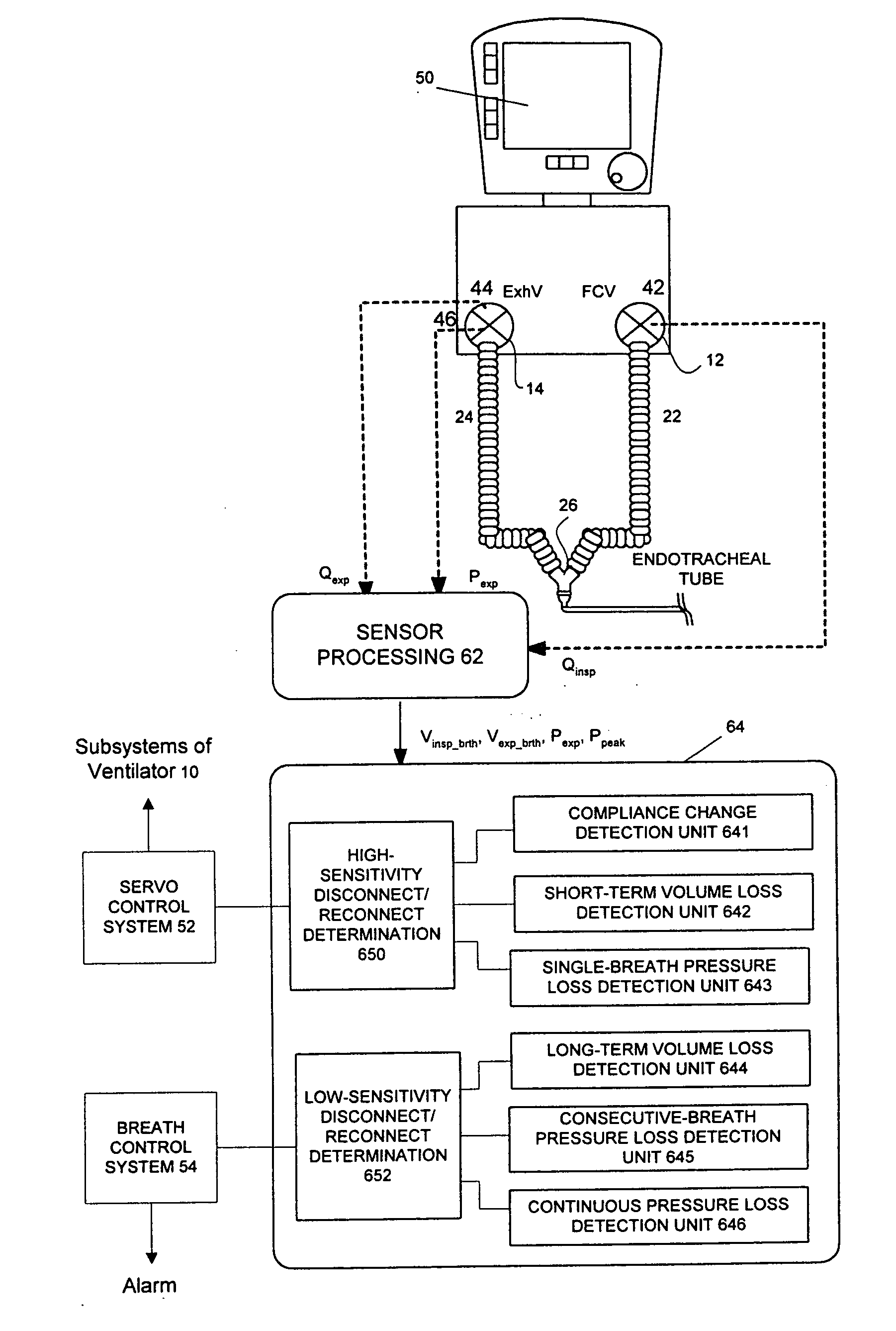
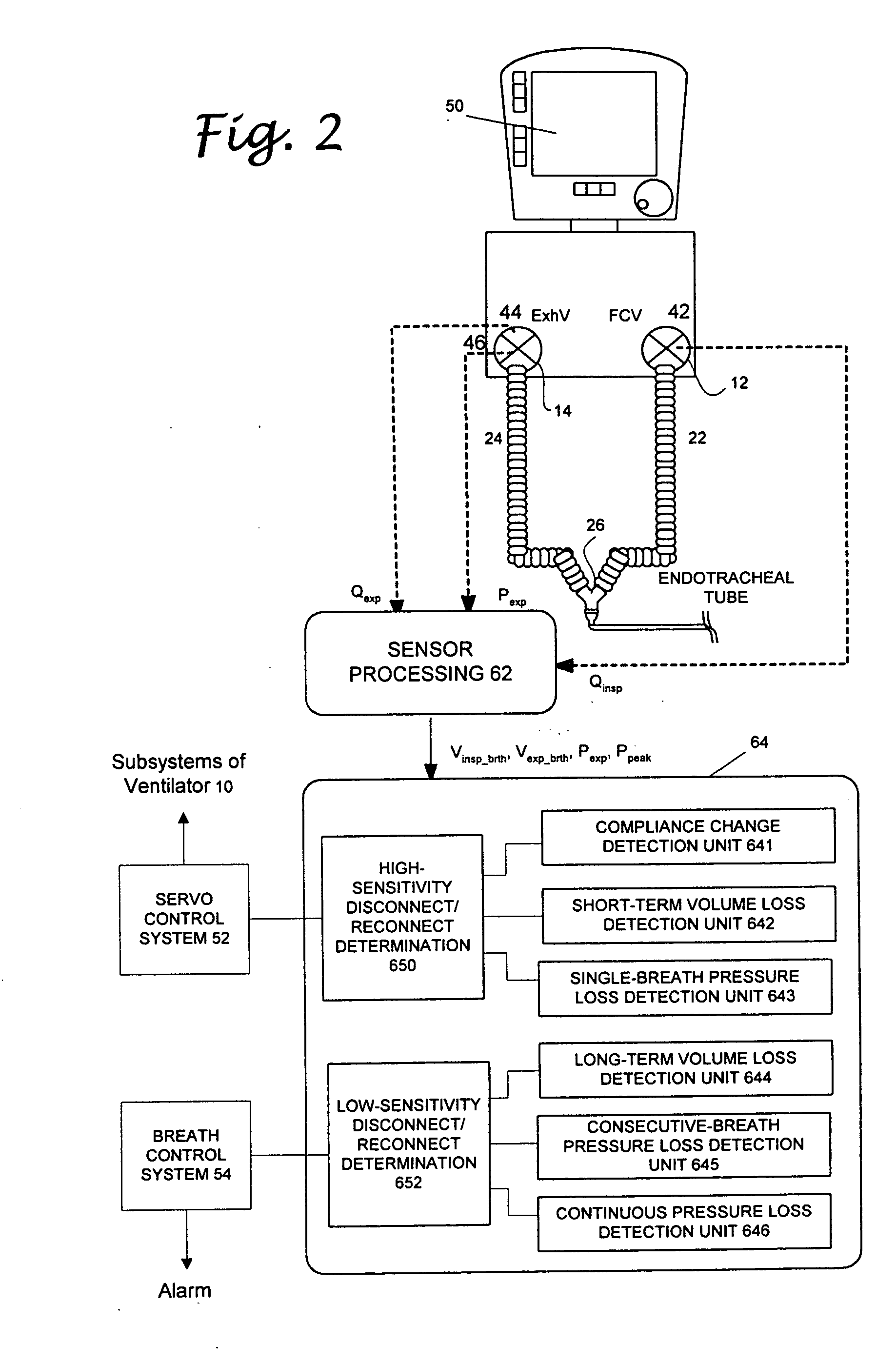
"The present invention provides an apparatus and method for detecting disconnects in a ventilation system in a reliable and timely manner. The invention uses two detection algorithms, one for the main alarm and another for a more reactive indication of a disconnect. The first detection algorithm requires at least one predetermined period of time or two consecutive breaths to detect the disconnect, while the second detection algorithm requires only one single breath. The first algorithm includes three sub-algorithms for detecting long-term volume loss, consecutive-breath pressure loss, and continuous pressure loss. The second algorithm also includes three sub-algorithms for detecting short-term volume loss, single-breath pressure loss, and compliance change. The invention provides a ventilation system comprising an inspiratory flow sensor, an expiratory flow sensor, an expiratory pressure sensor, and two sets of processing units for performing the detection algorithms. The invention allows for a more reliable and time-effective triggering of the main alarm and proper adjustment of the on-board sub-systems when a short-term disconnect occurs."

Problems solved by technology

When the volume leakage exceeds a predetermined percentage for the first predetermined period of time, a long-term volume loss is detected.

Method used


Image

  • Patient circuit disconnect system for a ventilator and method of detecting patient circuit disconnect
  • Patient circuit disconnect system for a ventilator and method of detecting patient circuit disconnect
  • Patient circuit disconnect system for a ventilator and method of detecting patient circuit disconnect

Examples


Embodiment Construction

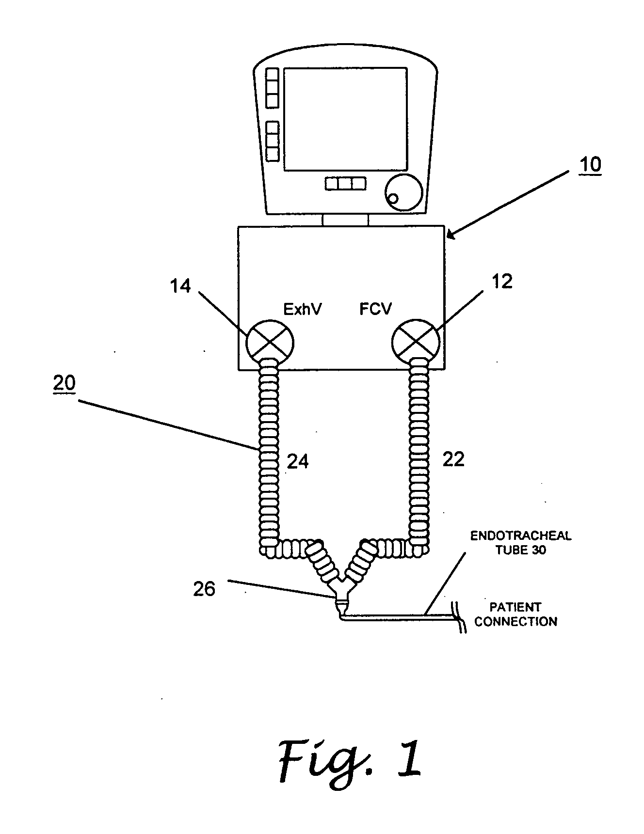
[0031] Referring now to the drawings wherein the showings are for purpose of illustrating preferred embodiments of the present invention only, and not for purposes of limiting the same, FIG. 1 shows a ventilation system which comprises a ventilator 10 and a patient circuit 20. The ventilator 10 has an inspiratory port 12 from which breathing gas is supplied to the patient circuit 20 and an expiratory port 14 for receiving gas exhaled from the patient through the patient circuit 20. The patient circuit 20 has an inspiratory line 22 connected to the inspiratory port 12 and an expiratory line 24 connected to the expiratory port 14. Both of the inspiratory line 22 and the expiratory line 24 are connected to a wye-fitting 26, which establishes the connection between the inspiratory and expiratory lines 22 and 24 to the patient via an endotracheal tube, mask or hood 30. Typically, the ventilator 10 has a pneumatic system for providing the breathing gas and an expiratory gas processing uni...


PUM


Abstract

A method of detecting disconnect of a patient circuit of a ventilation system, wherein a circuit disconnect is detected with a first sensitivity and a second sensitivity. The circuit disconnect detected with the first sensitivity is performed by detecting a volume loss for a minimum period of time, detecting a peak pressure loss for at least two consecutive breathing cycles or a minimum period of time, and detecting a pressure loss continuing for a predetermined period of time. The circuit disconnect detected with the second sensitivity is performed by detecting a volume loss for a single breathing cycle, detecting a pressure loss for a single breathing cycle, and detecting an increase of compliance. The first sensitivity is lower than the second sensitivity. Preferably, an alarm is activated when the circuit disconnect is detected with the first sensitivity, and subsystems of the ventilation system is informed of the circuit disconnect that has been detected with the second sensitivity.

Description

CROSS-REFERENCE TO RELATED APPLICATIONS [0001] Not Applicable STATEMENT RE: FEDERALLY SPONSORED RESEARCH / DEVELOPMENT [0002] Not Applicable BACKGROUND OF THE INVENTION [0003] The present invention relates in general to a method and a system for detecting a patient circuit disconnect of a ventilation system, and more particularly, to a method that not only detects patient circuit disconnect occurring in various locations of the circuit, but also informs critical subsystems of the ventilation system of the disconnect and / or a possible disconnect of the patient circuit. [0004] When a patient's respiratory system cannot provide adequate oxygenation and / or ventilation, a mechanical ventilation system is typically used to provide breathing gas, particularly, supplemental oxygen to a patient through a patient circuit. The patient circuit generally has an inspiratory line and an expiratory line connected to an inspiratory port and an expiratory port of a wye fitting. The wye fitting further ...

Claims


Application Information

Patent Timeline
Patent Type & Authority Applications(United States)
IPC IPC(8): A61M16/00
CPCA61M16/0051A61M2016/0021A61M2016/0039A61M2016/0042A61M16/0833A61M16/024
Inventor SOLIMAN, IHAB S.BRIGHTUP, VERN
Owner BIRD PRODS
Learn More