Light scanning unit

a scanning unit and light technology, applied in the field of light scanning units, can solve the problems of increasing vibration and affecting the vibration of the polygon motor

Inactive Publication Date: 2006-04-20
KK TOSHIBA +1
View PDF4 Cites 11 Cited by
  • Summary
  • Abstract
  • Description
  • Claims
  • Application Information

AI Technical Summary

Problems solved by technology

In the exposure unit disclosed in this publication, a polygon motor is directly fixed to a housing, so that a problem related to vibration of the polygon motor occurs.
In particular, when a large-sized polygon motor is adopted, or when the rotation speed of the polygon motor is high, ...

Method used


Image

  • Light scanning unit
  • Light scanning unit
  • Light scanning unit

Examples


Embodiment Construction

[0024] Throughout this description, the embodiments and examples shown should be considered as exemplars, rather than limitations on the apparatus of the present invention.

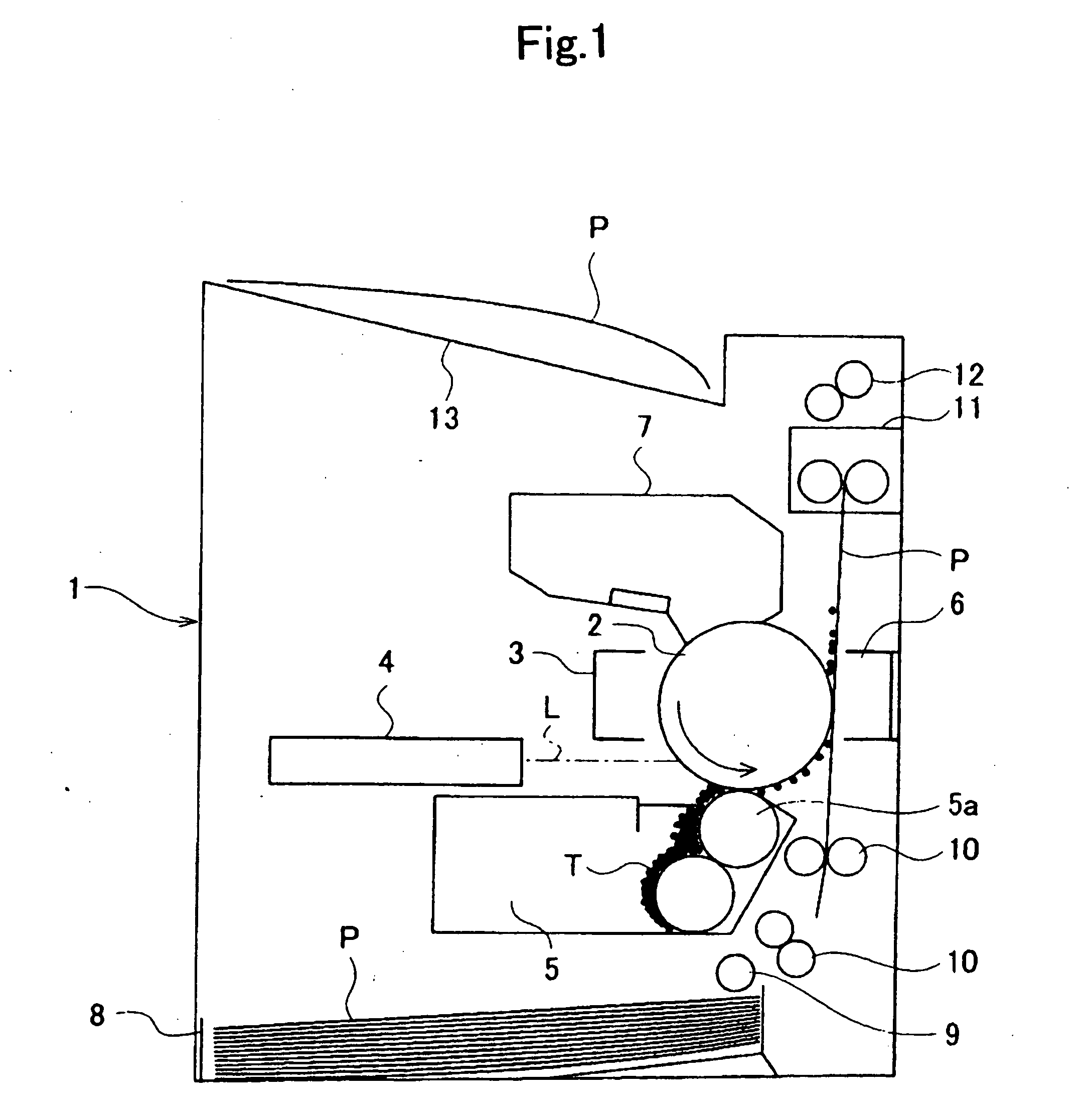
[0025]FIG. 1 is a view schematically showing a configuration of an image forming apparatus incorporating a light scanning unit according to an embodiment of the present invention. Firstly, with reference to FIG. 1, the entire configuration of an image forming apparatus using a light scanning unit according to the present invention will be described.

[0026]FIG. 1 shows an image forming apparatus that feeds a recording paper P from the lower side to upper side of the drawing to print an image on the recording paper P. As a developer, a magnetic toner is used. Reference numeral 1 is the main body of an image forming apparatus, and numeral 2 is a photoconductor drum. The photoconductor drum 2 is rotated, by a rotation drive unit(not shown), in the direction denoted by the arrow in the drawing. Around the photoconduct...


PUM


Abstract

A light scanning unit according to the present invention has a polygon motor that scans a laser beam emitted from a laser source, a plate that supports the polygon motor, and a cover that is fixed to the plate and covers the polygon motor. The polygon motor, plate, and cover constitute a motor block. The motor block is housed in a housing. The housing is made of synthetic resin. The plate and cover are made of metal. When a polygon mirror is attached to a circuit board and the base end of a motor shaft is inserted into a fix hole of the plate, the entire surface of the circuit board directly comes into contact with the plate surface.

Description

CROSS-REFERENCE TO RELATED APPLICATION [0001] This application is based upon and claims the benefit of priority from the prior Japanese Patent Application No. 2004-305806, filed on Oct. 20, 2004, and Japanese Patent Application No. 2005-065487, filed on Mar. 9, 2005, the entire contents of which are incorporated herein by reference. BACKGROUND OF THE INVENTION [0002] 1. Field of the Invention [0003] The present invention relates to a light scanning unit incorporated in an image forming apparatus that adopts an electrophotographic system for use in a fax machine or printer. [0004] 2. Description of the Related Art [0005] Some image forming apparatuses such as a fax machine or a printer adopt an electrophotographic system. In such an image forming apparatus, a charger, an exposure unit, a development unit, and a transfer unit are disposed around a photoconductor drum. The surface of the photoconductor drum is exposed by the charger while the photoconductor drum is being rotated to for...

Claims


Application Information

Patent Timeline
IPC IPC(8): B41J2/435
CPCG02B26/121
Inventor KOJIMA, TAKAHIRO
Owner KK TOSHIBA
Why Eureka
Try Eureka