Electrical-energy meter adaptable for optical communication with various external devices

a technology of electrical energy meters and optical communication, applied in the field of electrical energy meters, can solve the problems of limited readings and achieve the effect of facilitating optical communication

Inactive Publication Date: 2006-04-13
ELSTER ELECTRICTY LLC
View PDF17 Cites 15 Cited by
  • Summary
  • Abstract
  • Description
  • Claims
  • Application Information

AI Technical Summary

Benefits of technology

[0013] The invention may also include a method of configuring an electrical-energy meter for communication with an external device, comprising selecting an electrical-energy meter comprising, two optical transmitters, and one receiver, wherein the meter is capable of being configured to communicate with an external device, selecting a preconfigured template that covers one of the transmitters when the template is attached to the electrical-energy meter so that the other of the transmitters and the receiver facilitate optical communications between the electrical-energy meter and external device, and attaching the selected template to the electrical-energy meter so that the template's through holes are substantially aligned, respectively, with the electrical-energy meter's optical receiver and one of the electrical-energy meter's optical transmitters, and so that the electrical-energy meter's optical transmitter that is not substantially aligned with a template through-hole is blocked or covered-over by the template.

Problems solved by technology

Such readings have usually been limited to information regarding the electrical consumption of the customer.

Method used


Image

  • Electrical-energy meter adaptable for optical communication with various external devices
  • Electrical-energy meter adaptable for optical communication with various external devices
  • Electrical-energy meter adaptable for optical communication with various external devices

Examples


Embodiment Construction

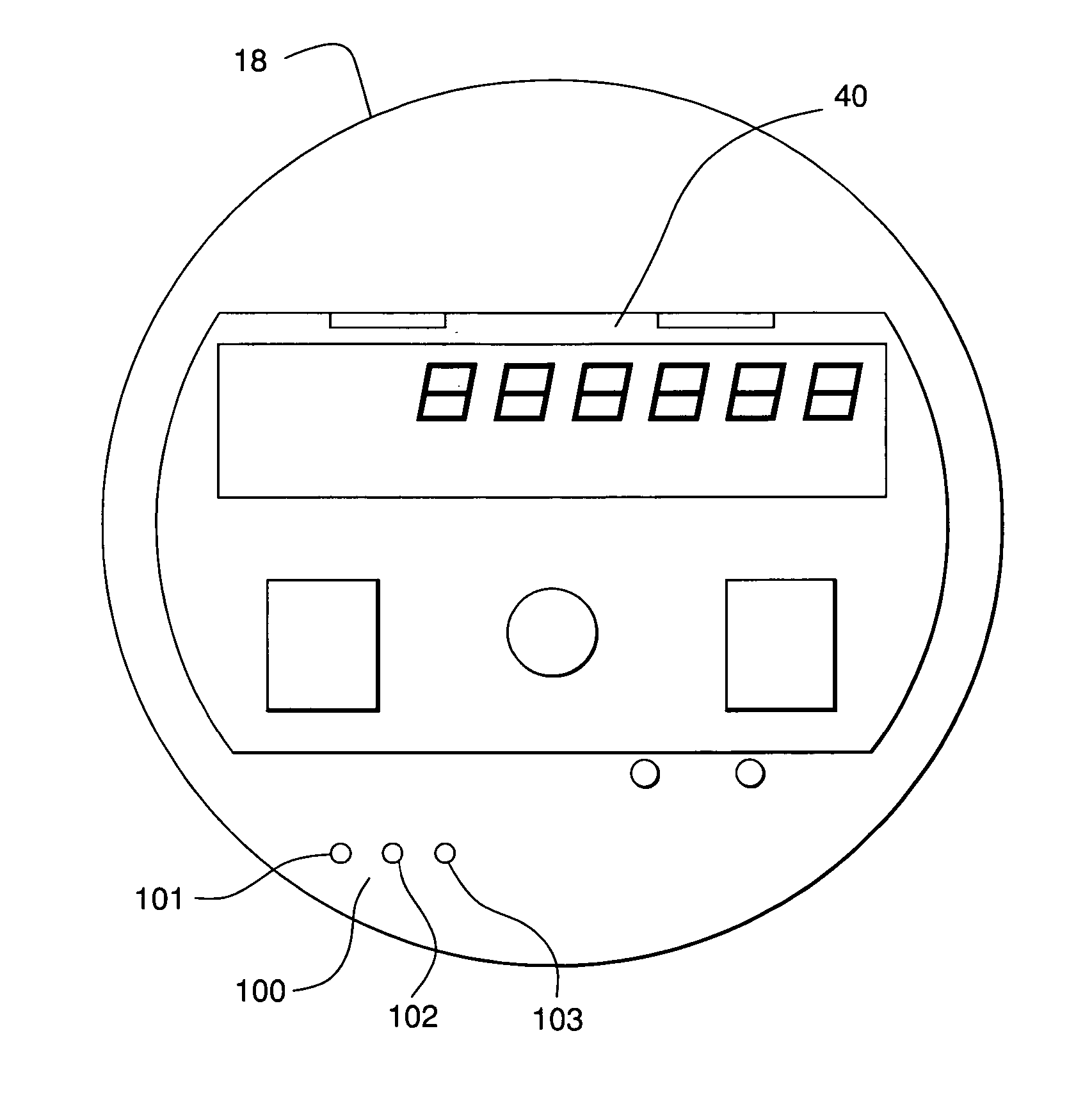
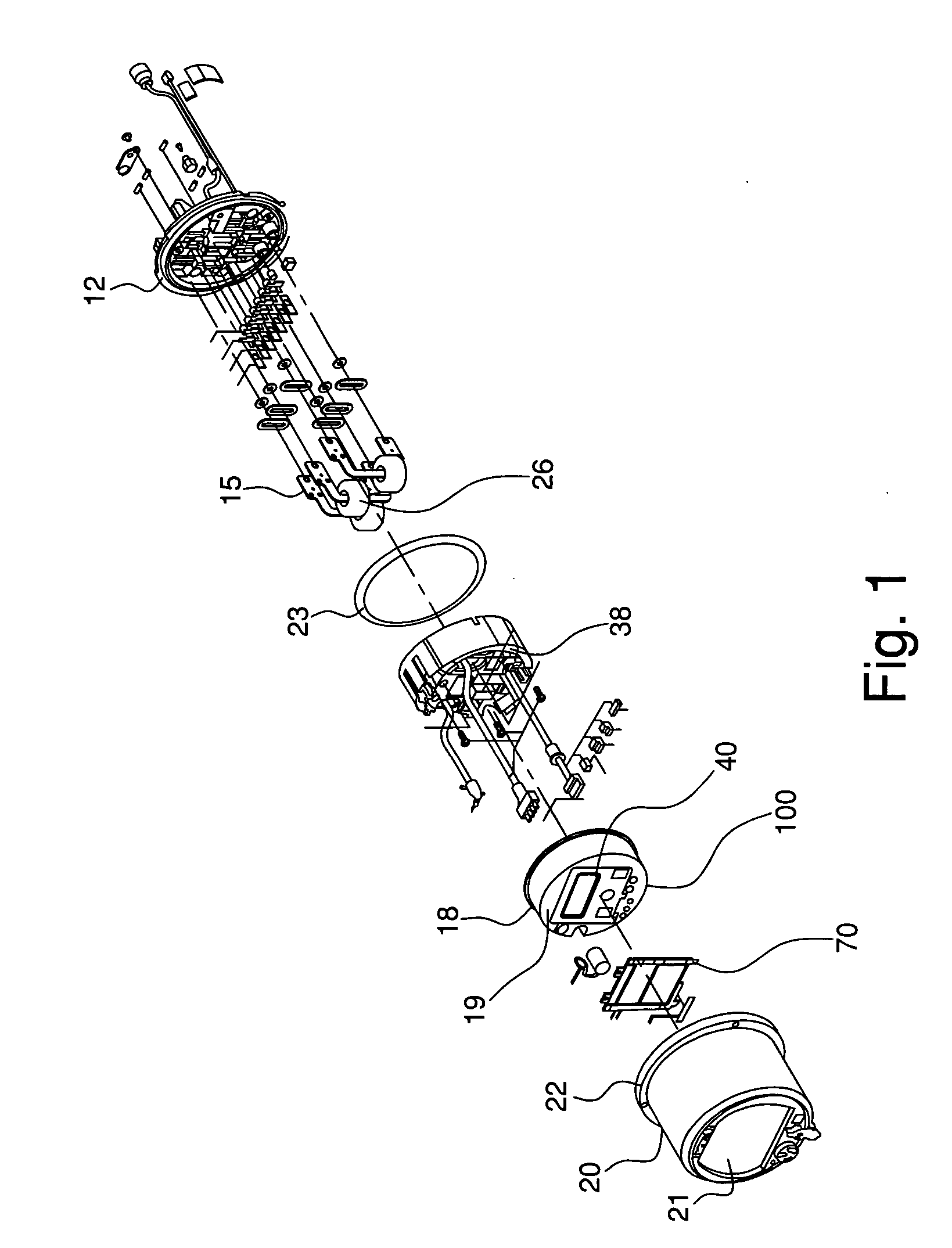
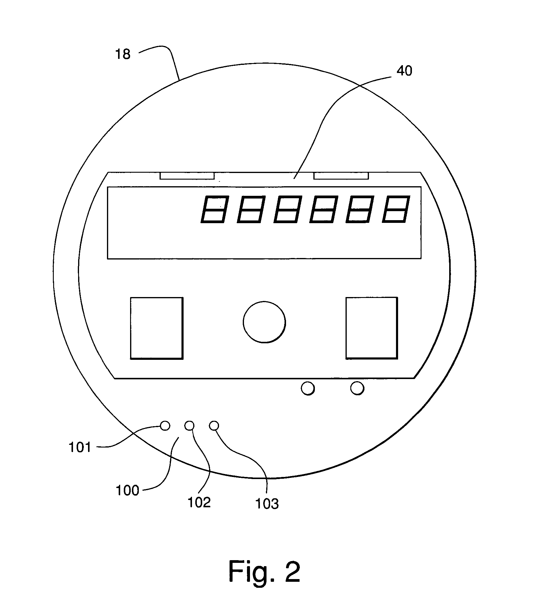
[0029] An example embodiment of an electrical-energy meter 10 is depicted in FIGS. 1-7. The electrical-energy meter 10 is described in detail for example purposes only, as the various features of the present invention can be incorporated into other types of electrical-energy meters.

[0030] The electrical-energy meter 10 comprises a cover 20 and optical templates 200, 300. (See FIGS. 4 and 6). Cover 20 as well as optical templates 200, 300 can be used in conjunction with virtually any type of electrical-energy meter, including electrical-energy meters of the electro-mechanical type. Additionally, electrical-energy meter 10 is a round shape consistent with electrical-energy meters constructed in accordance with ANSI. The invention, however, is not limited to such electrical-energy meters and may be used with electrical-energy meters constructed in accordance with other industry standards as well.

[0031] Electrical-energy meter 10 comprises a base 12, a current sensor assembly 15, a cu...


PUM


Abstract

An example embodiment of an electrical-energy meter comprises a transformer for producing an electrical output proportional to an electrical current in a conductor of electrical energy, a circuit board electrically coupled to the transformer for facilitating the calculation and displaying of a cumulative amount of electrical energy passing through the conductor of electrical energy, a first optical transmitter, a second optical transmitter, and an optical receiver. The first and second optical transmitters and the optical receiver are coupled to the circuit board. The first optical transmitter and the receiver facilitate optical communications between the electrical-energy meter and a first type of external device. The second optical transmitter and the receiver facilitate optical communications between the electrical-energy meter and a second type of external device.

Description

FIELD OF THE INVENTION [0001] The present invention relates to electrical-energy meters, also referred to as “watt-hour meters” or “power meters,” for measuring consumption of electrical power. More particularly, the invention relates to optical communications between electrical-energy meters and external devices. BACKGROUND OF THE INVENTION [0002] The reading of electrical-energy meters has historically been accomplished with human meter readers who visit a customer's premises and manually document relevant information from the meter. Such readings have usually been limited to information regarding the electrical consumption of the customer. Over time, manual meter reading has been enhanced or eliminated through the use of meter reading systems. In one example of a meter reading system, a probe is held in proximity to and communicates with the meter. The communication between the probe and the meter is two way and involves an exchange of information beyond just the electrical consu...

Claims


Application Information

Patent Timeline
Patent Type & Authority Applications(United States)
IPC IPC(8): G01R11/32G01R35/04
CPCG01R21/133G01R22/063G01R22/00
Inventor WEIKEL, SCOTT J.LINDQVIST, LARS A.
Owner ELSTER ELECTRICTY LLC
Why Eureka
Try Eureka