
System and method for monitoring tool usage

Inactive Publication Date: 2006-04-06
GENERAL ELECTRIC CO
View PDF14 Cites 48 Cited by
  • Summary
  • Abstract
  • Description
  • Claims
  • Application Information

AI Technical Summary

Problems solved by technology

For example, wear and tear on the measuring device caused by the use of the measuring device may cause the device over time to begin providing erroneous measurements.
In addition, certain measuring devices and tools may have a limited lifetime and must be replaced once the lifetime of the measuring device or tool is complete.
However, this is not an efficient scheme for maintaining a measuring device calibrated as the tool may sit unused for significant periods of time.
Therefore, the measuring device is not experiencing the type of usage that would tend to cause the device to begin providing erroneous measurements.
Thus, the device may become un-calibrated due to excessive usage.
However, this method is also inefficient, as it also does not accurately reflect actual wear and tear on the device.
However, these types of manual data collection methods are usually inefficient and can lead to errors in data collection and analysis.
As a result, a tool may be checked for calibration too infrequently and thereby become un-calibrated before its scheduled calibration check.
Alternatively, the tool may be checked for calibration too frequently, thereby adding unnecessary expense and loss of productivity.
In addition, attempts have been made to schedule preventative maintenance or even tool replacement using similarly inefficient methods.
Furthermore, such attempts have been in a manner that either obstructs or interferes with the normal course of production.
Consequently, these methods reduce the efficiency of production.

Method used


Image

  • System and method for monitoring tool usage
  • System and method for monitoring tool usage
  • System and method for monitoring tool usage

Examples


Embodiment Construction

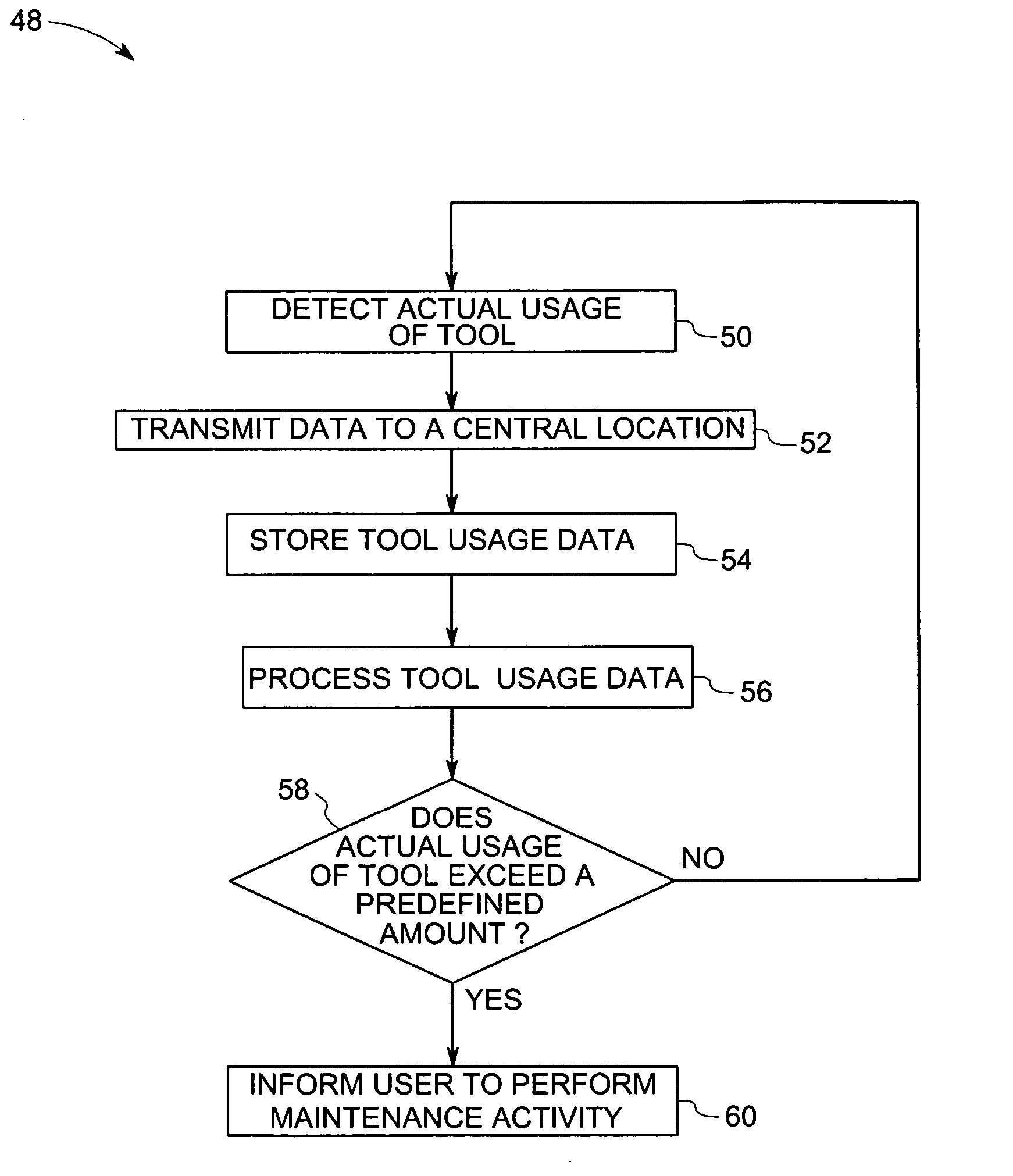
[0022] In the subsequent paragraphs, various aspects of a technique for automatically monitoring the usage of a tool in a workplace will be explained. The various aspects of the present techniques will be explained, by way of example only, with the aid of figures hereinafter.

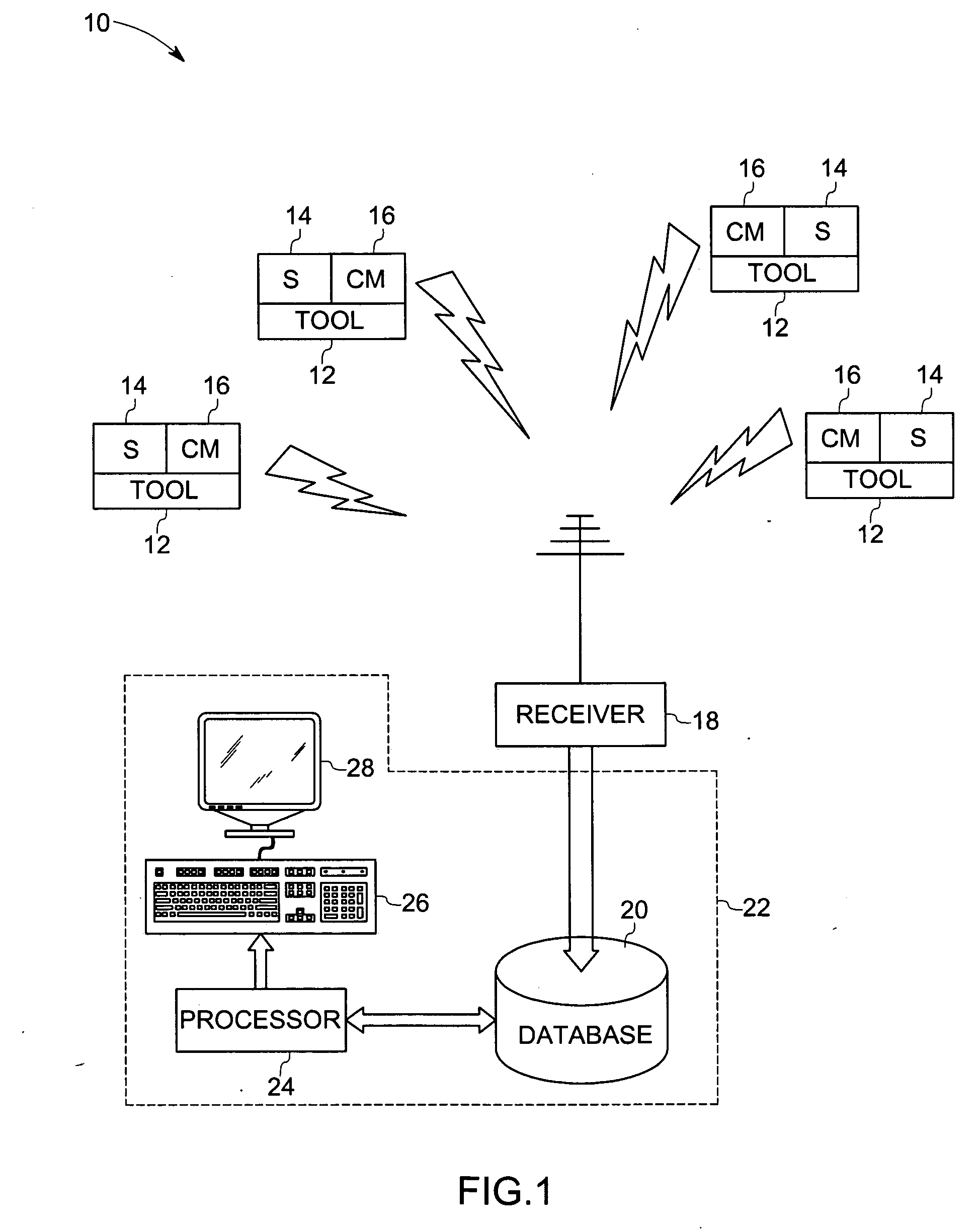
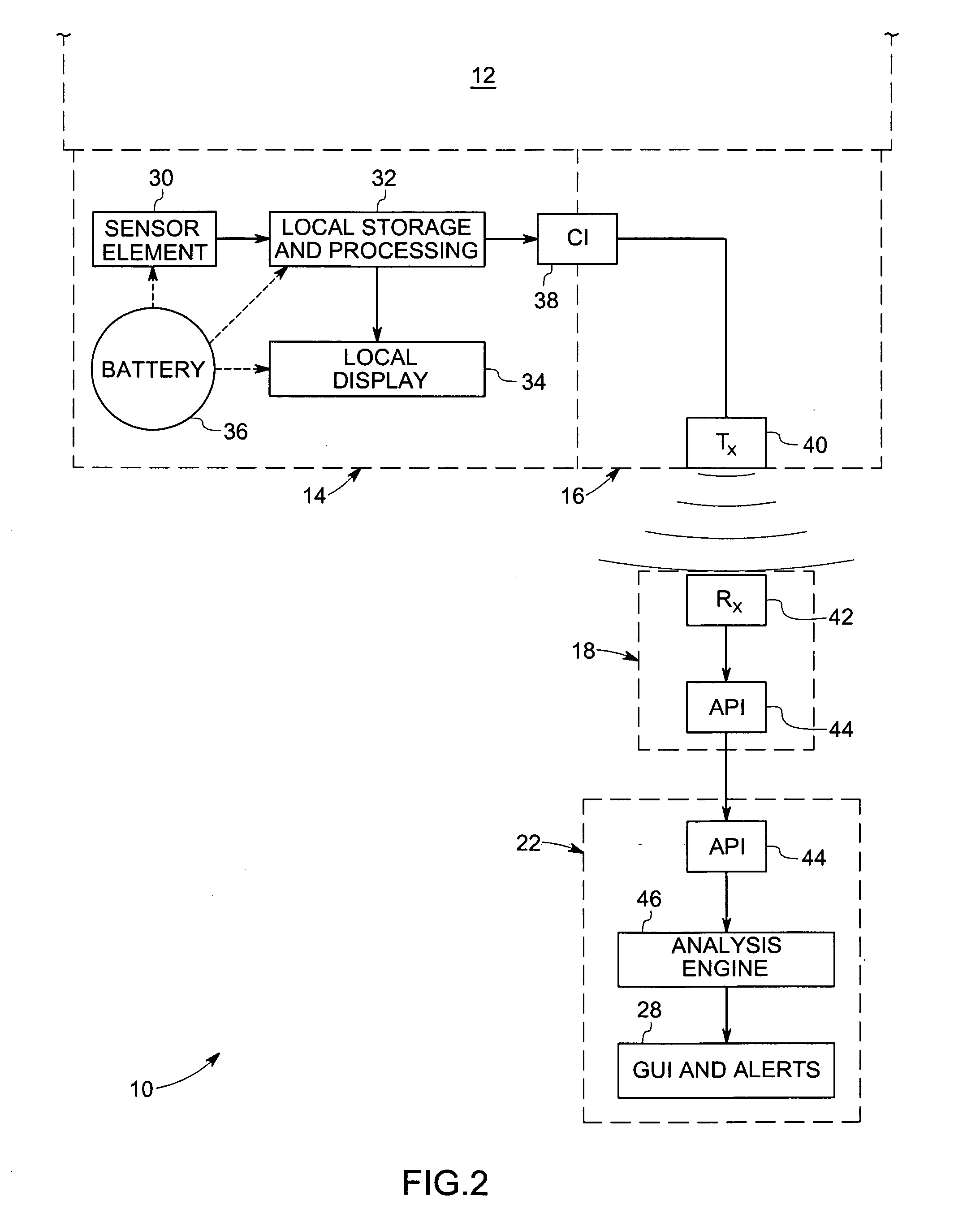
[0023] Referring generally to FIG. 1, an illustration of a centralized tool usage monitoring system 10 is shown. The tool usage monitoring system 10 may be used to monitor usage of tools, calibrated devices, such as gages and meters, and the operation of various devices. In FIG. 1, a plurality of tools 12 is located at various locations in a production facility. Each of the tools 12 is coupled with a hardware interface or sensor 14 that is operable to detect when the tool 12 is in use. Each of the tools 12 has a unique identifier. The unique identifier may be a unique number that is used to distinguish each tool and its corresponding hardware interface 14. The unique identifier facilitates tracking and monitori...


PUM


Abstract

A tool usage monitoring system and method is provided. The system comprises a sensing element for detecting when a tool is in use and producing a signal representative of tool usage. A processor-based device that is communicatively coupled to the sensing element is also provided. The processor-based device is programmed to maintain a running total of tool usage based on the signal representative of tool usage. The processor-based device also is operable to store a defined tool usage total corresponding to the tool. The system further comprises a user interface coupled to the processor-based device. The processor-based device is programmed to send a signal to the user interface when the running total of tool usage either equals or exceeds the defined tool usage total. The system is also capable of monitoring usage of a plurality of tools.

Description

BACKGROUND [0001] The invention relates generally to tool usage monitoring systems, and more particularly to a system and method for monitoring tool usage for calibration verification or replacement purposes. [0002] A measuring device typically is calibrated to ensure that the device will provide an accurate measurement when it is used to take a measurement. Calibration is a process to standardize a measuring device by determining the amount of deviation between a measurement taken by the measuring device and a standard. The deviation of the measurement from the standard is then used to apply a correction factor to the measuring device so that the measuring device produces an accurate measurement. It may be desirable to periodically check the calibration of the measuring device and / or re-calibrate the measuring device. For example, wear and tear on the measuring device caused by the use of the measuring device may cause the device over time to begin providing erroneous measurements....

Claims


Application Information

Patent Timeline
IPC IPC(8): G06F19/00
CPCG07C3/00
Inventor DEROSE, LYNN ANNMACKENZIE, PATRICIA DENISEFORMAN, DOUGLAS ROY
Owner GENERAL ELECTRIC CO
Learn More