
Rocking exercise apparatus

Inactive Publication Date: 2006-04-06
MATSUSHITA ELECTRIC WORKS LTD
View PDF6 Cites 14 Cited by
  • Summary
  • Abstract
  • Description
  • Claims
  • Application Information

AI Technical Summary

Benefits of technology

[0009] An object of the present invention is to provide a rocking exercise apparatus which can perform complicated movements to give a larger fitness effect while being small in size and inexpensive.

Problems solved by technology

H06-65350, the operation timings, speeds, operation ranges of the respective driving sources are separately controlled, therefore a fairly complicated control is necessary.
Further, since six driving sources are provided, there are additional problems that the apparatus tends to be enlarged and production cost is high.
Further, since the seat can make only three kinds of movements including reciprocating linear movements of the seat along longitudinal direction, reciprocating pivotal movements thereof about the longitudinal axis and reciprocating pivotal movements thereof about the transverse axis according to the technology of Japanese Unexamined Patent Publication No. 2004-216072, the movements become monotonous.

Method used


Image

  • Rocking exercise apparatus
  • Rocking exercise apparatus
  • Rocking exercise apparatus

Examples


first embodiment

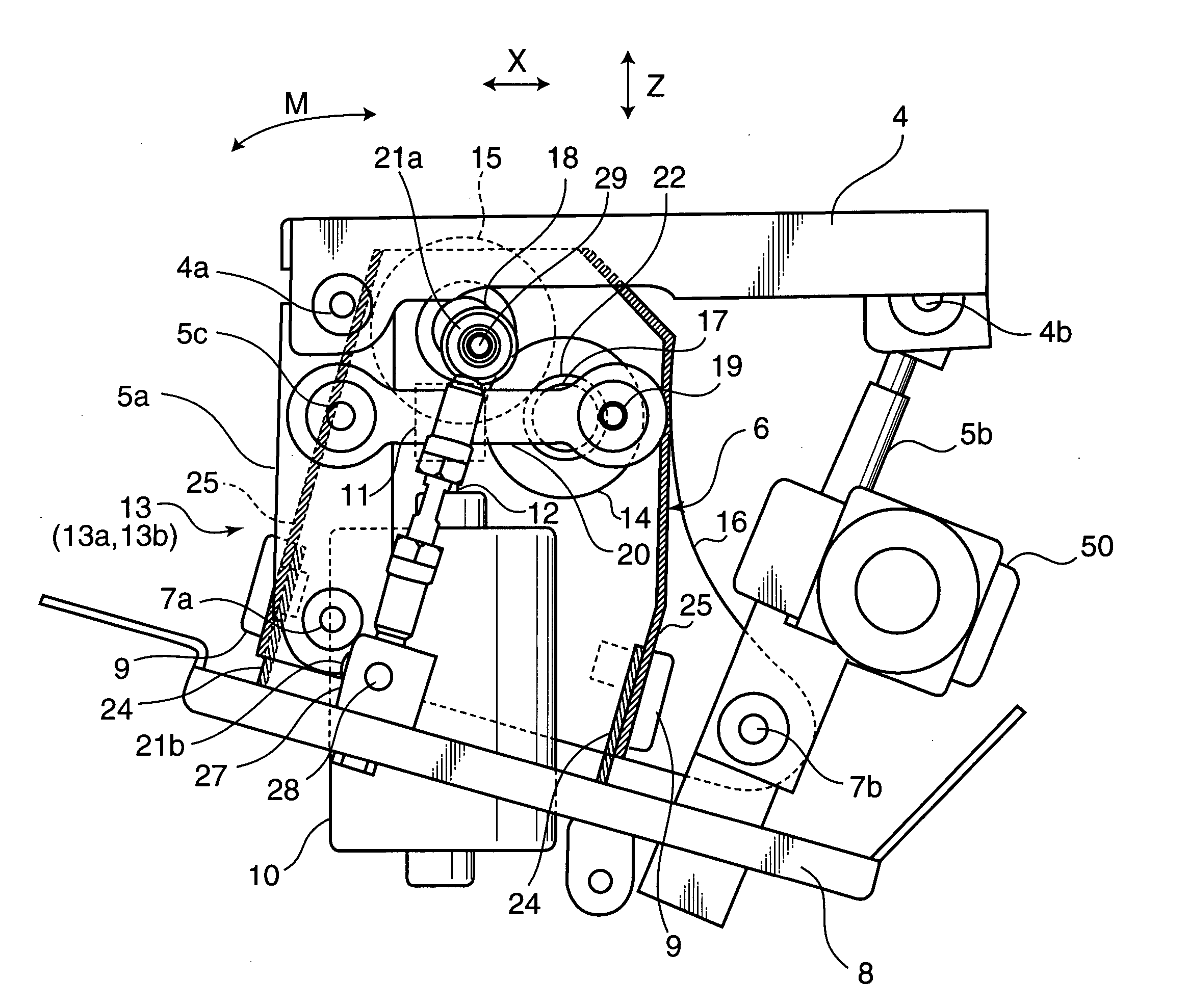
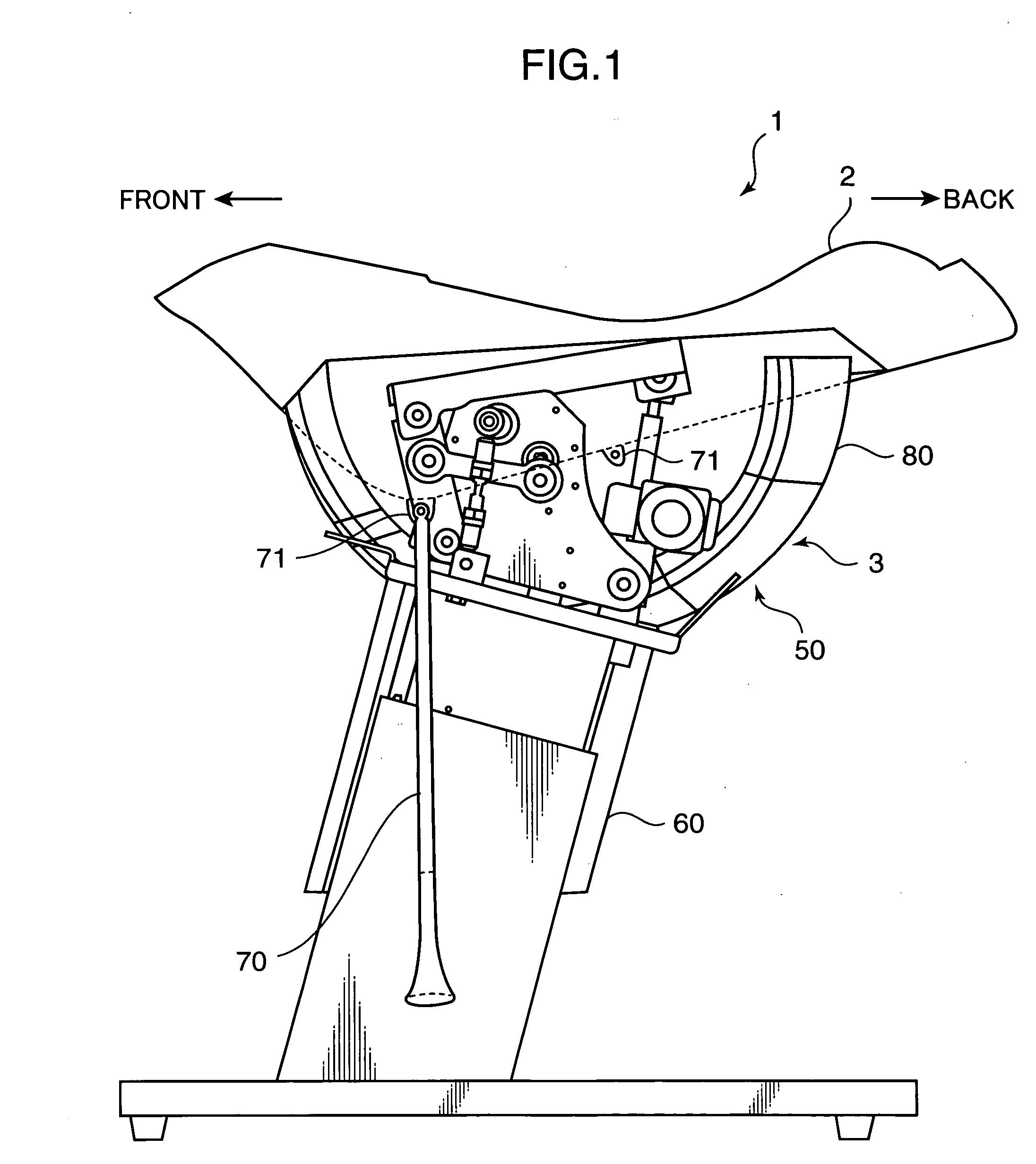
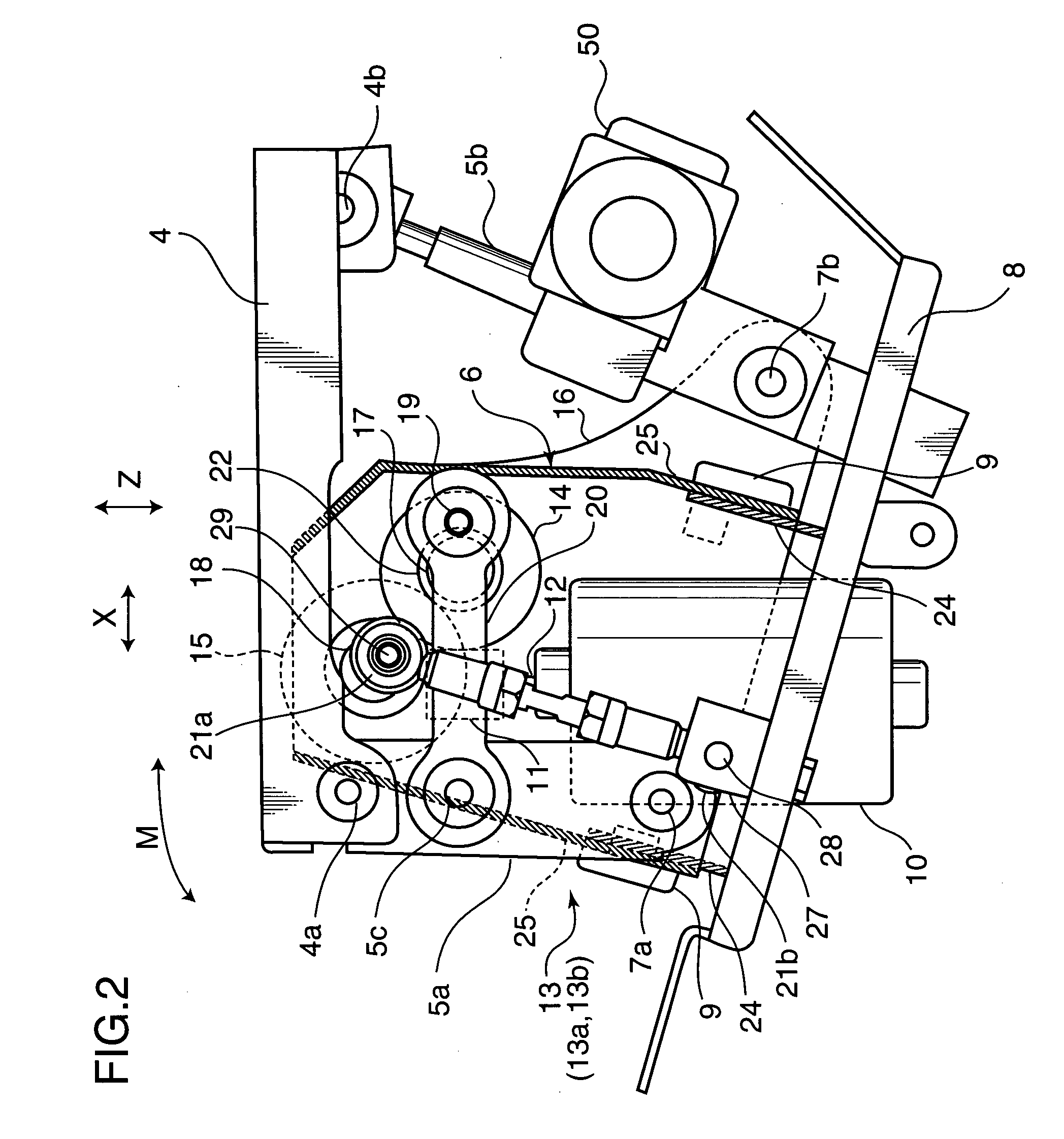
[0020]FIG. 1 is a side view showing the entire construction of a rocking exercise apparatus according to a first embodiment of the present invention. This rocking exercise apparatus 1 is provided with a seat 2 having the shape simulating a horseback or a saddle and to be seated by a user, a driving unit 2 as a rocking mechanism provided in the seat 2 to rock the seat 2, an elevating mechanism 50 for moving a rear part of the seat 2 upward and downward, a leg portion 60 supporting the seat 2 and the driving unit 3, stirrups 70 for resting the user's feet and a cover 80. In order to provide a better comfort when the user is seated on the seat 2, the stirrups 70 are preferably suspended near the center below the seat 2 when the seat 2 is horizontal while being suspended near positions right below a supporting point of rotation 4a of a pedestal 4 when the seat is inclined forward as shown in FIG. 1. Accordingly, mount seats 71 are provided at two positions in the middle and the bottom b...

second embodiment

[0030] Although four kinds of movements are made possible by providing the longitudinally inclined shafts 9 in the first embodiment, a function of inclining forward and backward may be added to the conventional three kinds of movements disclosed in Unexamined Patent Publication No. 2004-216072. FIG. 6 is a side view showing the entire construction of a driving unit of a rocking exercise apparatus 1a according to a second embodiment.

[0031] In FIG. 6, a pedestal 4 on which a seat 2 is mounted is so supported on a movable mount 6 via connection links 5a, 5b as to rock forward and backward (first supporter), wherein the movable mount 6 is so supported on a horizontal base 8 as to rock to left and right (second supporter) and a driving device 13 is accommodated between the pedestal 4 and the movable mount 6. The connection links 5a are front links provided at the left and right sides of the pedestal 4, whereas the connection link 5b is a rear link provided in the widthwise center of the...

third embodiment

[0042] A transverse inclining function may be added to the conventional three kinds of movements disclosed in Unexamined Patent Publication No. 2004-216072. FIG. 8 is a side view showing the entire construction showing a driving unit of a rocking exercise apparatus 1b according to a third embodiment. Here, no repeated description is given since the construction other than an elevating mechanism 50a is the same as in the second embodiment.

[0043] The elevating mechanism (changer, extending and contracting mechanism) 50a has a construction similar to the one shown in FIG. 7, but differs from the one of the second embodiment in being inserted in an eccentric rod 21c of the rocking exercise apparatus 1b.

[0044] The elevating mechanism 50a operates as follows.

[0045] When an output rotary shaft 52a of a motor 51 is rotated, a worm wheel 53 is rotated by the engagement with a worm gear 52 while being supported by bearings 54. Then, a nut 55 fitted to the worm wheel 53 rotates together wit...


PUM


Abstract

A rocking exercise apparatus is provided with a motor and a driving unit for translating a torque of an output rotary shaft of the motor into rocking movements of a seat seated by a user. This driving unit includes a first supporter for supporting a movable mount provided on a base such that the movable mount can make reciprocating pivotal movements about a longitudinal shaft inclined with respect to longitudinal direction; a second supporter for supporting a pedestal fixedly attached to the seat such that the pedestal can make reciprocating pivotal movements about transverse shafts provided in the movable mount via connection links; a first driving portion for translating the rotary motion of the output rotary shaft of the motor into reciprocating linear movements of the pedestal along longitudinal direction and reciprocating pivotal movements about a transverse axis via the second supporter; and a second driving portion for translating the rotary motion of the output rotary shaft of the motor into reciprocating pivotal movements of the pedestal about a longitudinal axis and reciprocating pivotal movements about a vertical axis via the first supporter. An angle of inclination of the movable mount with respect to a center axis of the reciprocating pivotal movements in at least either one of the first and second supporters is changeable. Accordingly, the rocking exercise apparatus can give a larger fitness effect by complicating the movements while being small and inexpensive.

Description

BACKGROUND OF THE INVENTION [0001] 1. Field of the Invention [0002] The present invention relates to a rocking exercise apparatus for giving exercise loads to a user by letting a seat make rocking movements with the user seated on the seat. [0003] 2. Description of the Related Art [0004] Rocking exercise apparatuses for giving exercise loads to users by letting seats make rocking movements with the users seated on the seats as above have been spread from health or fitness clubs where these apparatuses have been initially used to general households as convenient exercise apparatuses usable from children to the old. Typical prior arts of such rocking exercise apparatuses are disclosed, for example, in Japanese Examined Patent Publication No. H06-65350 and Japanese Unexamined Patent Publication No. 2004-216072. [0005] The technology disclosed in Japanese Examined Patent Publication No. H06-65350 relates to a training apparatus for preventing low back pain by realizing a series of rocki...

Claims


Application Information

Patent Timeline
IPC IPC(8): A63B22/00A63B71/00
CPCA63B21/0058A63B23/0211A63B23/0227A63B23/0233A63B26/003A63B69/0053A63B69/04A63B2069/0062A63B69/0062A63B22/16A63B22/04
Inventor NAKANISHI, RYUSUKE
Owner MATSUSHITA ELECTRIC WORKS LTD
Learn More