
Monitoring device for welding wire supply

a monitoring device and wire supply technology, applied in the field of wire packages, can solve the problems of unexpected exhaustion of welding wire on the spool, damage to the contact tip of the welding torch, and possible failure or rejection of the weld, and achieve the effect of convenient us

Inactive Publication Date: 2006-04-06
LINCOLN GLOBAL INC
View PDF6 Cites 67 Cited by
  • Summary
  • Abstract
  • Description
  • Claims
  • Application Information

AI Technical Summary

Benefits of technology

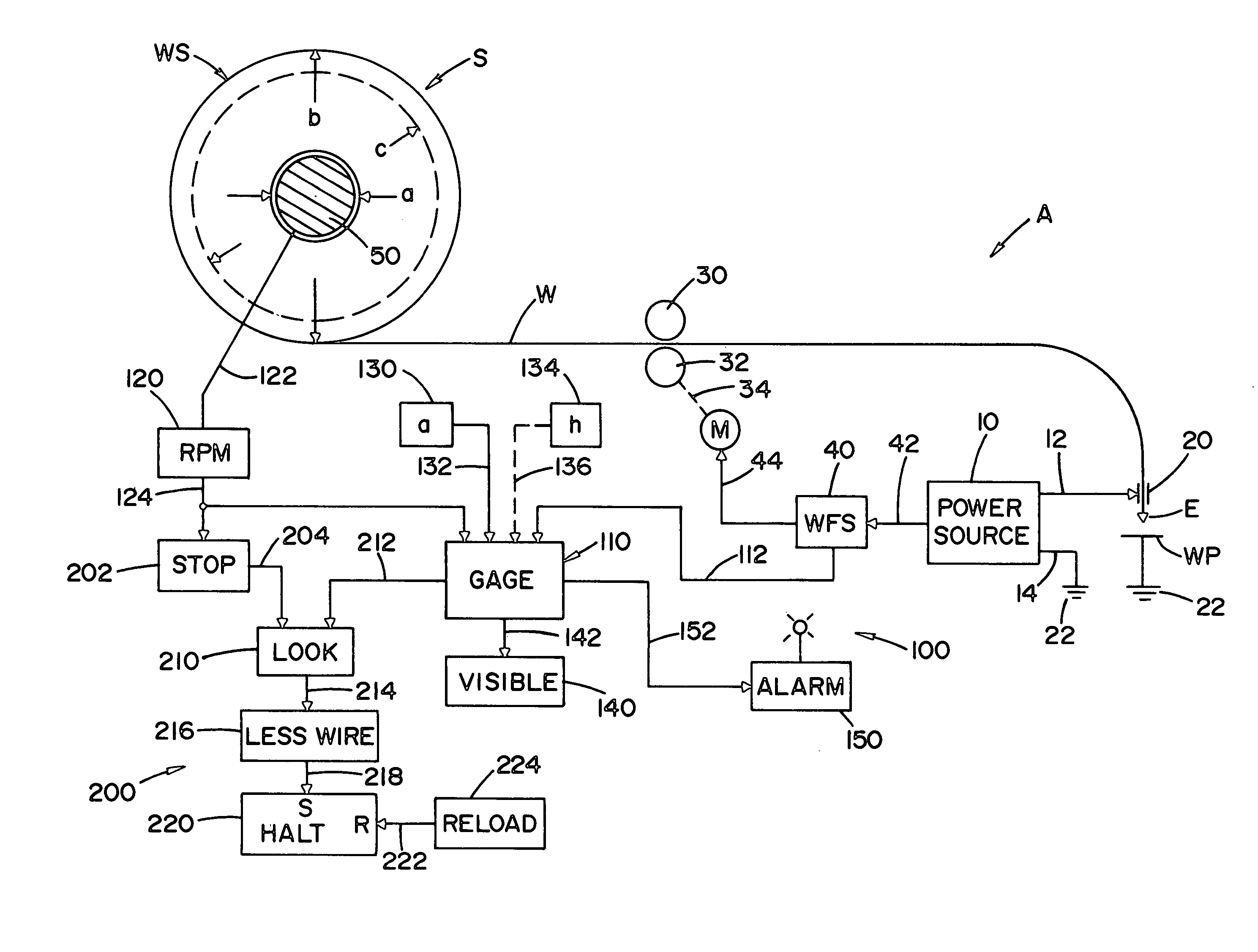
The invention is a monitoring device for real-time sensing the actual amount of welding wire on a spool in a wire feeder of an electric arc welder. The device uses a sensor to measure the speed of the spool, which is proportional to the amount of wire on the spool. This relationship is used to create a signal indicative of the actual wire supply. The device can display the wire supply level in real-time, allowing for timely adjustments to the spool. The invention provides a more accurate indication of the wire supply level than traditional methods, which can help improve the efficiency of the welding process.

Problems solved by technology

The use of a spool as a package is convenient for storage and for general use on high production welders; however, when using a spool, serious problems occur when the supply of welding wire on the spool is unexpectedly exhausted.
Consequently, the depletion of the welding wire from a spool often results to damage to the contact tip of the welding torch and possibly failure or rejection of the weld.
This deficiency has substantial consequences when the welding operation is in a production line operated on the “just in time” basis.
At this time, there is no device that can be associated with an electric arc welder to monitor the actual supply of welding wire available for the welding operation, except for a suggestion of weighing the spool and wire.
Weighing the spool requires a complicated device for mounting the rotating spool on a scale mechanism.
This arrangement is not acceptable.
There are advantages in the Blankenship approach, but it is not now employed for measuring the amount of wire on a rotating spool.

Method used


Image

  • Monitoring device for welding wire supply
  • Monitoring device for welding wire supply
  • Monitoring device for welding wire supply

Examples


Embodiment Construction

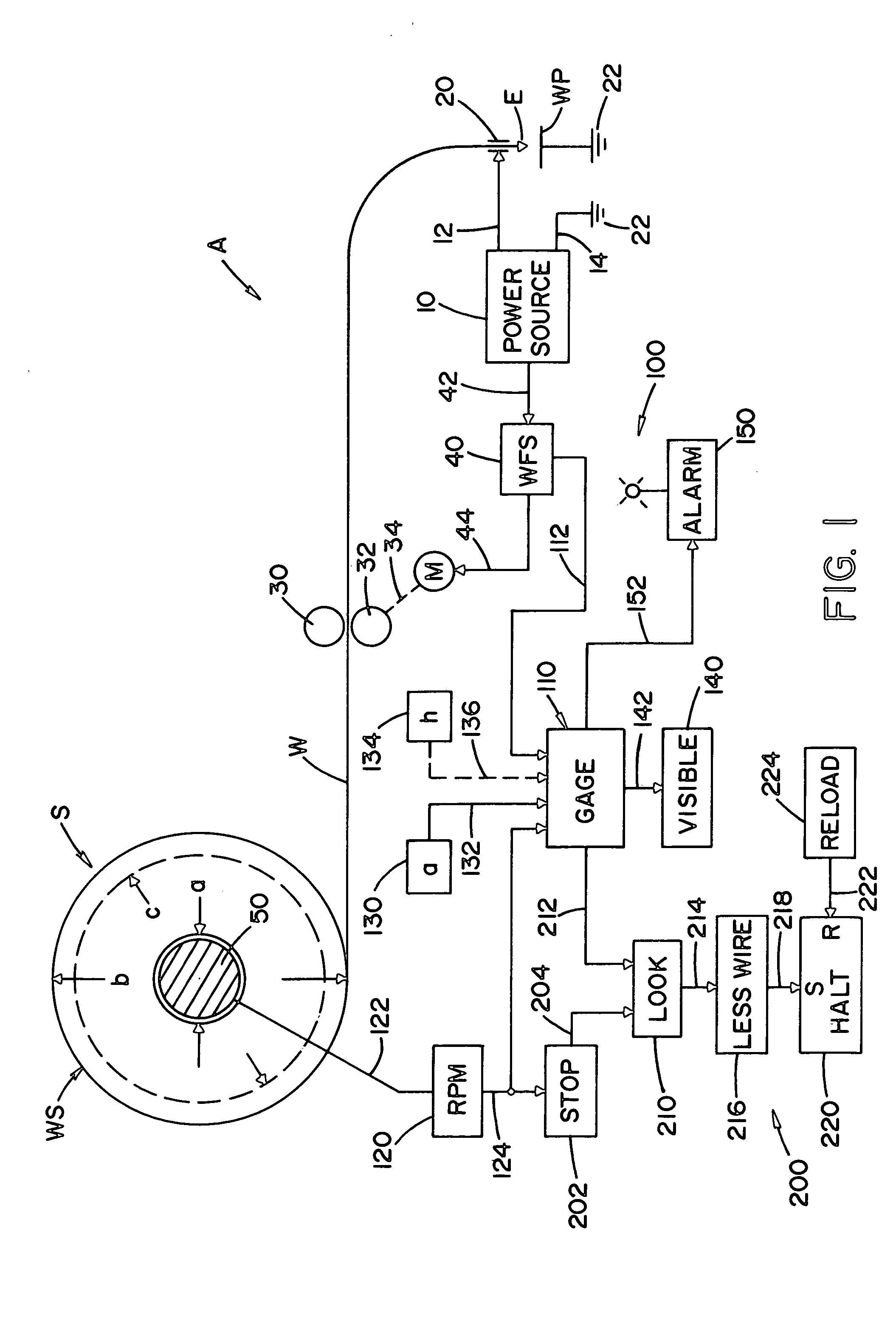
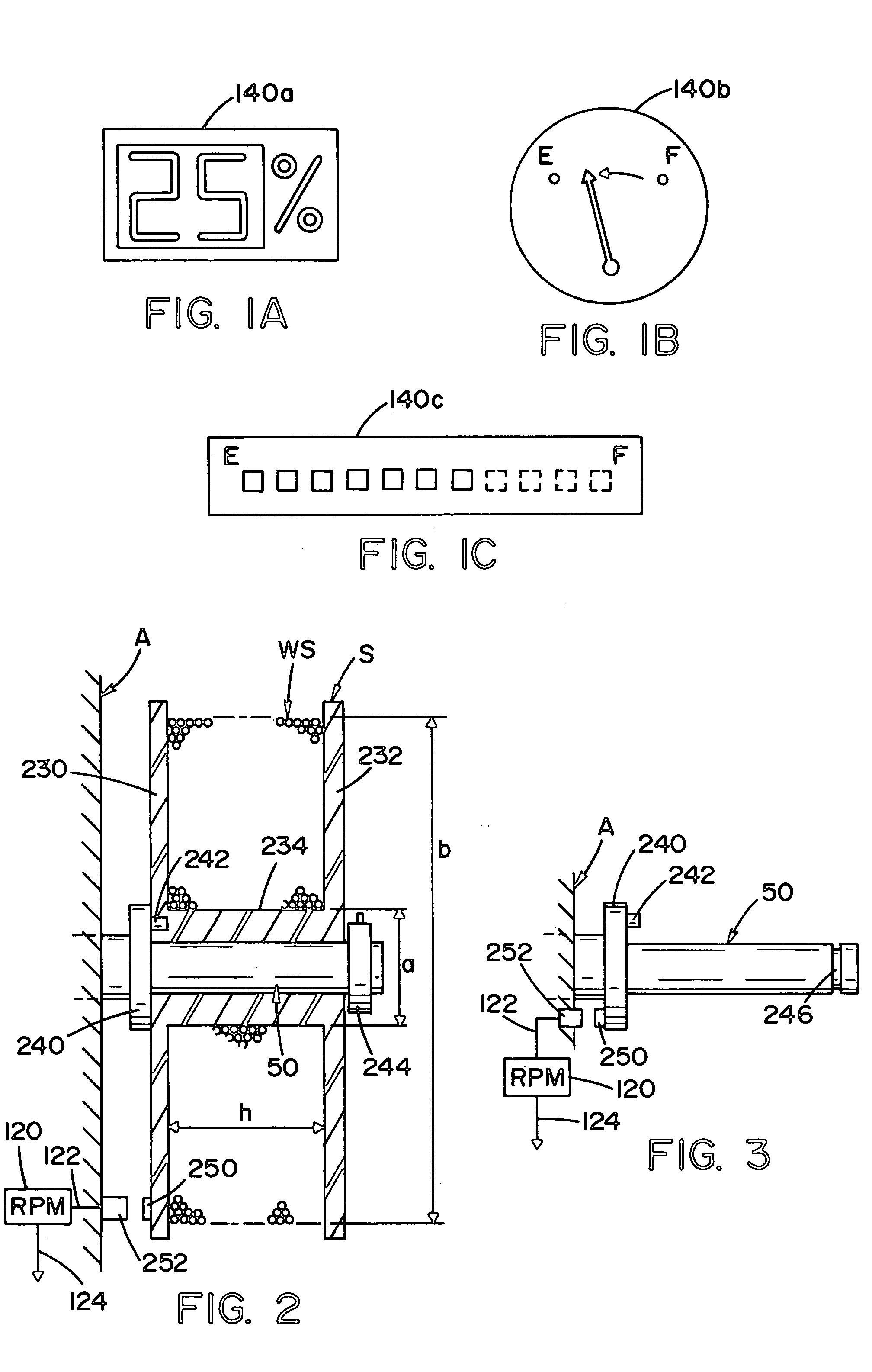
[0040] Referring now to the drawings wherein the showings are for the purpose of illustrating a preferred embodiment of the invention only and not for the purpose of limiting same, FIG. 1 illustrates schematically an electric arc welder A having a standard power source 10 with output terminals 12, 14 for the purpose of directing electrical welding current to torch 20 to pass a current between electrode E in the form of an advancing wire W and workpiece WP. Power source 10 and workpiece WP are grounded at ground 22 to perform a welding operation comprising a series of welding cycles. Each welding cycle requires a given amount of wire W provided from a standard spool S rotatably mounted on spindle 50 of the wire feeder associated with welder A. The supply of wire WS on spool S progresses from a maximum volume or a volume defined by diameter b to a minimum volume defined by diameter a. The real time or actual amount of wire on spool S is indicated by volume determined by diameter c. Of...


PUM

PropertyMeasurementUnit
timeaaaaaaaaaa
diameteraaaaaaaaaa
speedaaaaaaaaaa

Abstract

A monitoring device for sensing of the actual amount of welding wire on a spool with a minimum wire supply diameter for use in a wire feeder of an electric arc welder, said monitoring device comprising: an RPM device to create a spool speed signal indicative of the rotational speed of the spool as the spool provides wire at the known wire feed speed and a converting device for converting according to a set relationship the spool speed signal into a wire supply signal varying between a high level when the spool speed signal is low at a presumed maximum supply of wire on the spool and a low level when the spool speed signal is high at the minimum supply of wire on said spool determined by the minimum wire supply diameter.

Description

[0001] The present invention relates to electric arc welding of the type using a continuous supply of welding wire and more particularly to a monitoring device for the welding wire supply during operation of the welder. INCORPORATION BY REFERENCE [0002] It is known to monitor the amount of wire in a supply drum from which wire is pulled by a wire feeder for use in an electric arc welder as shown in Blankenship U.S. Pat. No. 6,708,877, incorporated by reference herein as background information. The amount of wire in the drum supplying welding wire to the wire feeder is recorded on the drum and a measuring device measures the amount of wire used and subtracts this amount from the recorded amount of wire supplied with the welding wire drum. Similar devices have been suggested for weighing the spool or drum to determine when the weight is reduced to a low level. These two techniques for determining the amount of wire in a welding wire supply package are incorporated herein as background...

Claims


Application Information

Patent Timeline
Patent Type & Authority Applications(United States)
IPC IPC(8): B23K9/10
CPCB23K9/12B23K9/124
Inventor DANIEL, JOSEPH A.
Owner LINCOLN GLOBAL INC
Learn More