Eureka AIR delivers breakthrough ideas for toughest innovation challenges, trusted by R&D personnel around the world.

Folding knife

a folding knife and folding technology, applied in the field of folding knives, can solve the problems of increasing the cost and complexity of folding knives by adding additional features

Inactive Publication Date: 2006-03-30
OY FISKARS AB
View PDF99 Cites 82 Cited by
  • Summary
  • Abstract
  • Description
  • Claims
  • Application Information

AI Technical Summary

Problems solved by technology

Adding additional features increases the cost and complexity of the folding knife.

Method used


Image

  • Folding knife
  • Folding knife
  • Folding knife

Examples


Embodiment Construction

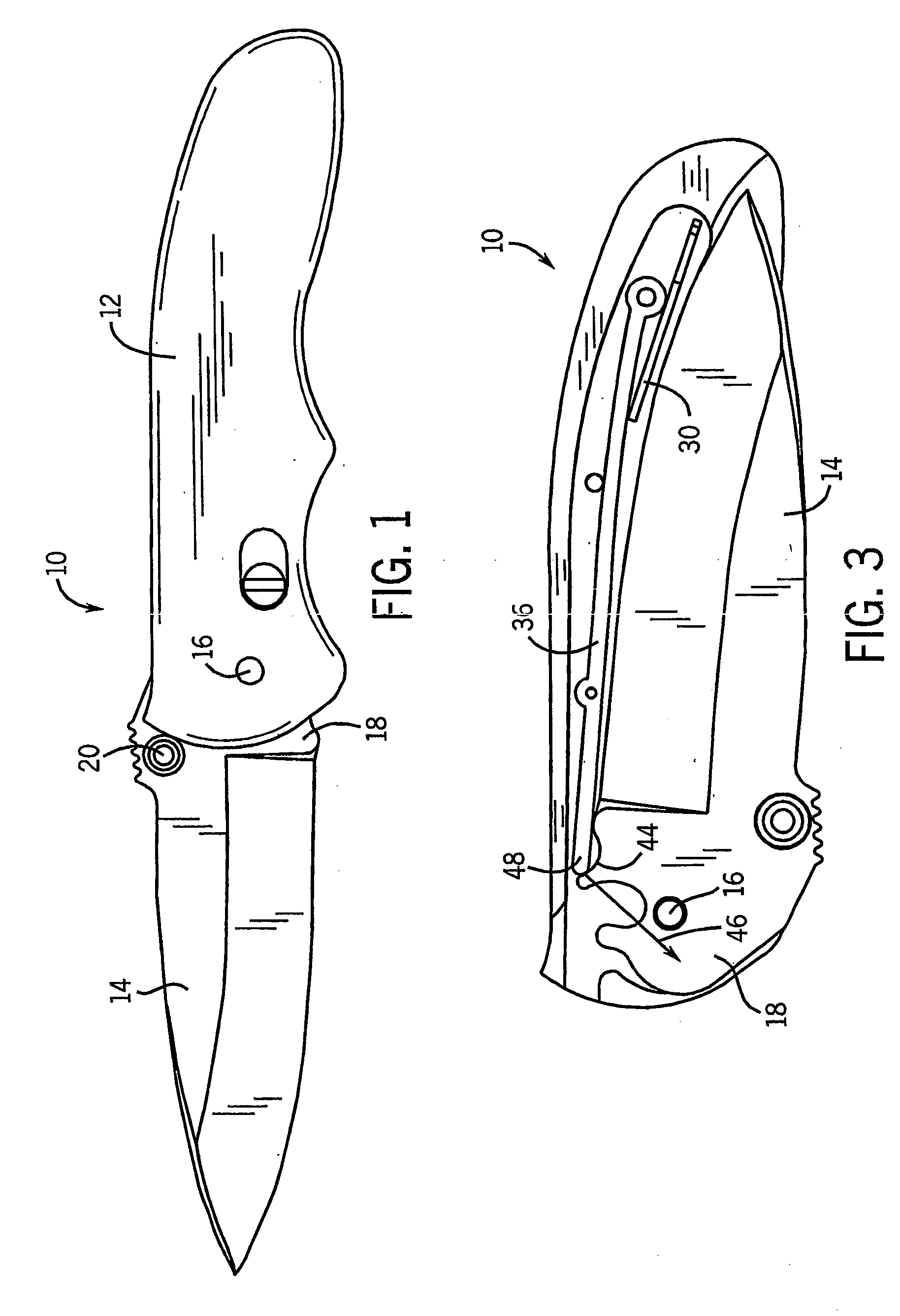
[0020] Referring to FIG. 1, a knife, shown as folding knife 10, includes a handle 12 pivotally coupled to an implement, shown as, but not limited to blade 14. The blade 14 is coupled to the handle by a blade axle 16 that extends through a tang 18 of the blade. A thumb stud 20 may extend outwardly from a portion of the blade for gripping by the user.

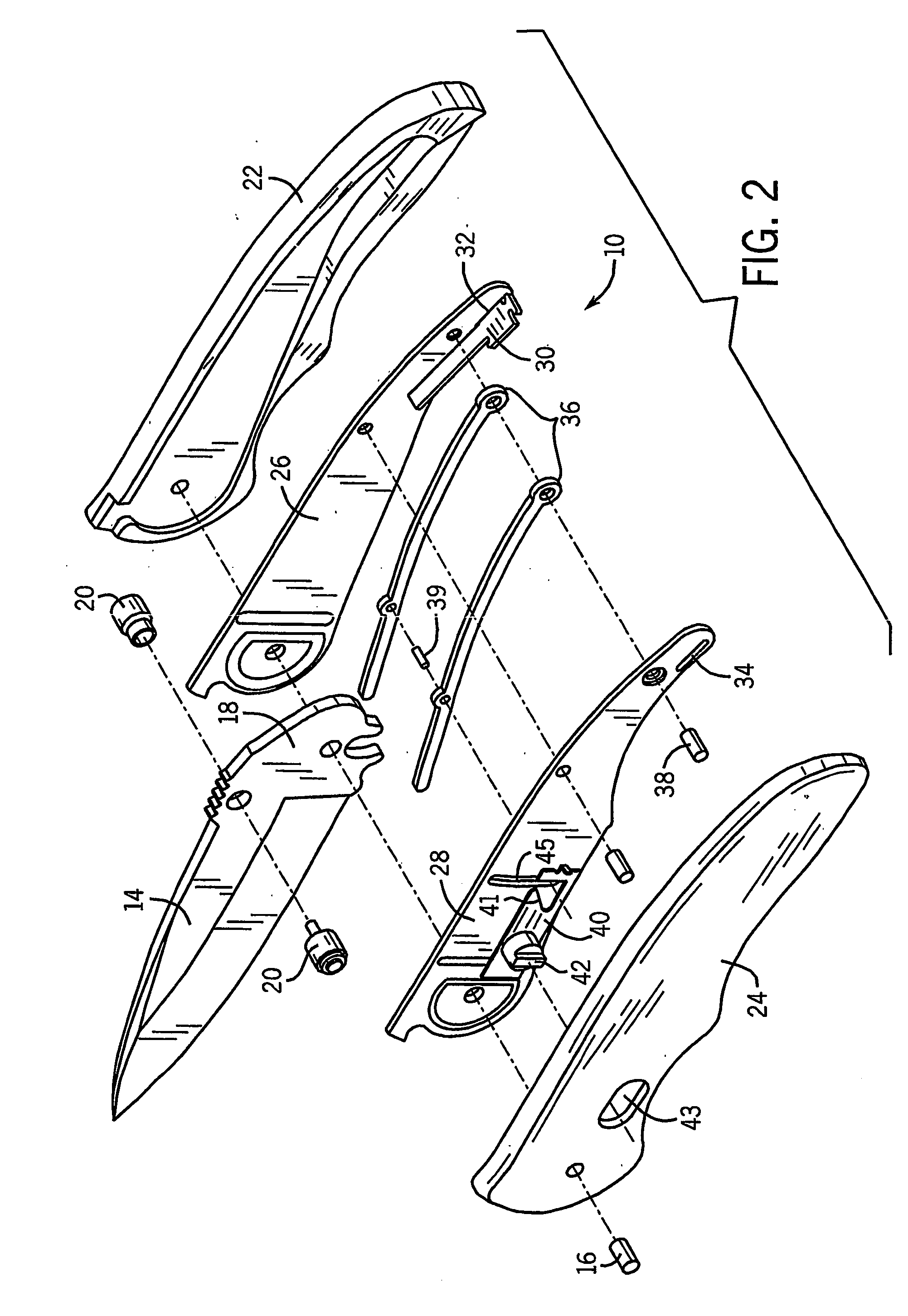
[0021] Referring to FIG. 2, in an exemplary embodiment, folding knife 10 is enclosed by a pair of handle sides 22, 24. Liners 26, 28 fit within handle sides 22, 24. A leaf spring 30 is coupled to liners 26, 28 by engaging with slots 32, 34 and liners 26, 28. A spring arm 36, which may comprise one or more pieces, is coupled to liners 26, 28 via pivot axle 38. An unlocking mechanism, shown as unlocking latch 40, may be disposed between handle side 24 and liner 28 and include a knob 42 that extends through an aperture 43 in handle side 24. A rod 39 may extend through spring arm 36 and through a slot 45 in liner 28 such that it may engage u...


PUM


Abstract

A folding tool includes a handle and an implement pivotally coupled to the handle according to one embodiment. The implement is adapted to travel between a closed position and an open position and has a tang with a contoured surface. A spring arm has a first end coupled to the handle and a second end adapted to interact with the implement. The spring arm exerts an opening force on the implement during at least a portion of the travel of the implement between the closed position and the open position and also locks the implement into the open position.

Description

CROSS-REFERENCE TO RELATED APPLICATIONS [0001] This application claims the benefit of U.S. Provisional Application No. 60 / 416,830, filed Oct. 8, 2002, which is incorporated herein by reference in its entirety.FIELD OF THE INVENTION [0002] The present invention relates to a folding knife. In particular, the present invention relates to a folding knife having a mechanism used to assist the user in opening the knife. BACKGROUND OF THE INVENTION [0003] Folding knives typically include a handle and one or more blades pivotally attached to the handle, the blades having a compact closed position and an extended open position. A user opens the blade by grasping the blade or pushing a knob protruding from the blade in order to rotate the blade into the open position. [0004] Additional features are added to folding knives in order to make such knives more useful and easier to operate. Such features may include a mechanism used to assist the user in opening the knife, a mechanism used to lock ...

Claims


Application Information

Patent Timeline
IPC IPC(8): B26B3/06F41B13/02B26B1/04
CPCB26B1/048B26B1/04
Inventor VALLOTTON, ALNEYKDALLAS, EDGARA
Owner OY FISKARS AB
Why Eureka
Eureka Blog
Learn More